


Section
8
Transmitter Calibration and
LTM Troubleshooting
8.0 Calibration
There really is no need to re-calibrate this
instrument. The LTM-Series arrive calibrated
to specified measuring ranges at order
placement.
If the need arises and a recalibration is deemed
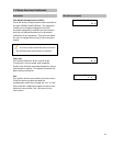
necessary please follow these instructions carefully.
Level simulation will be required at 0% and
100% positions.
1. Verify the “probe length” is not the same as
the” measuring range” desired. If so please
change accordingly.
See Sections 2.1 and 7.1.
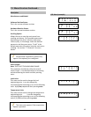
2. Go to the “Change Range” menu and set
the desired URV (measuring range).
3. Go to the “Trim Sensor” menu and enter.
4. At the “Trim Zero” screen place the level (or
magnet/float) at 0% (4mA point) and then
press enter.
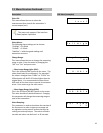
5. At the “Trim Span” screen place the level
(or magnet/float) at 100% (20mA point) and
then press enter.
6. “Exit” the configuration menus and the
instrument should be calibrated. If not
begin to troubleshoot or consult factory for
assistance.
Error Preventative Calibration: The LTM-250/350
transmitters are protected from incorrect
calibration so if something is done incorrectly it will
display “Span Error” on the LCD for 5 seconds and
then return to the beginning of the “Trim Sensor”
menu.
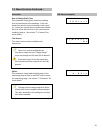
Recommendation: Again there is no need to
recalibrate the instrument simply go to the
“Change Range” menu and adjust the LRV or URV
as desired.
8.1 Troubleshooting
Magtech manufactures custom built products so
each transmitter has been specifically designed to
fit on a magnetic level gage or be inserted into a
tank/vessel and has been approved by the end user
at some point during the ordering/purchasing
process. Each transmitter has been factory
calibrated to meet end user requirements so there
is no need to recalibrate these transmitters unless
the requirements have changed from the time of
purchase/delivery to installation. If the need arises
to calibrate these units to a new range please
carefully read and follow the calibration procedure
in the instruction and operation (I/O manual) or
consult the factory. Always feel free to contact the
factory if any questions or uncertainties arise. The
following guide has been established to guide the
end user through some troubleshooting procedures
if the need arises.
There are 3 basic scenarios that can potentially
cause issues. They are:
1.
Physical damage to the sensor probe.
Accidents can happen during the installation
process and if the sensor is permanently bent,
bowed, or kinked it will no longer work
properly. Some symptoms of damage to the
sensor probe are:
a. Erratic output, unit jumping to full scale
(alarm mode) randomly, usually around
the damage point.
b. Unit in constant alarm condition
c. Unit going into alarm condition after a
certain point.
If the unit arrives damaged please contact
factory immediately.
28