


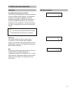


7.2 Features (Exclusive to the LTM-250/350 models)
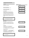
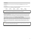
Change Signal (ChngSgnl): The next and final menu in the special features menu is “ChngSgnl” or change
signal option. The feature allows the adjustment of the signal being sent down the sensor probe. It can be
utilized when one electronics module is being utilized to save settings for various different length sensor probes.
This menu has 3 parameters that can be adjusted. The first is “Energy” [%], it is increased for a longer sensor
probe and decreased for a shorter sensor probe. The second parameter is “DCOffset” or DC Offset [v], this
parameter is decreased for longer sensor probes and increased for shorter sensor probes. The third (and final)
parameter is the “HoldTime” or hold time [us], this parameter recommended to stay within a certain range.
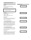
There is purposely not much detail on this option as it is recommended that these parameters not be
changed unless the electronics module is being utilized for more than one sensor probe. It is also
recommended that the user be guided by the factory if this option is being utilized.
This option is also intended for mainly factory use. Changing these parameters can cause undesirable
results. Please consult factory with any questions. The “factory” default configurations can be loaded if the
parameters have been drastically changed.
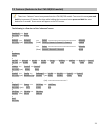
Pulse Width Filter (PW Filtr): The pulse width filter can be utilized for dual output (level and interface)
applications if there are any erroneous readings being transmitted or displayed. This feature can be adjusted so
the unique signal from the magnetic float can be concentrated on and all other false signals are ignored.
This option/feature only appears in software revisions 1.01.15 or higher.
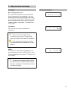
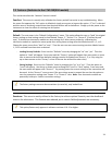
Conversion from Gage Mount to Standalone: When converting from a gage mount transmitter to a
standalone transmitter or vice versa simply contact the factory to order appropriate parts. Please have the
serial number of the transmitter documented so the factory can make traceable record changes and offer better
assistance. Most conversions can now be done in-field with minor configurations and calibration.
Converting from gage mount to standalone: Remove the transmitter from the gage, then remove
4/20mA (or 0/100%) stickers from the sensor probe. Call factory with serial number and desired process
connections (3/4”mnpt, 2”mnpt hex plug, flanges, etc…).
Converting from standalone to gage mount: Remove the transmitter from the vessel, then remove
process connections and float. Call factory with serial number of transmitter and the level gage to which
the transmitter is to be mounted.
Always be careful not to damage the sensor probe when removing/installing the transmitter to/from the
gage or vessel.
27