


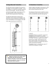
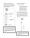
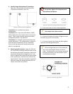
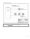
2. Identify Proper Orientation of Transmitter:
There are a few possible orientations of the
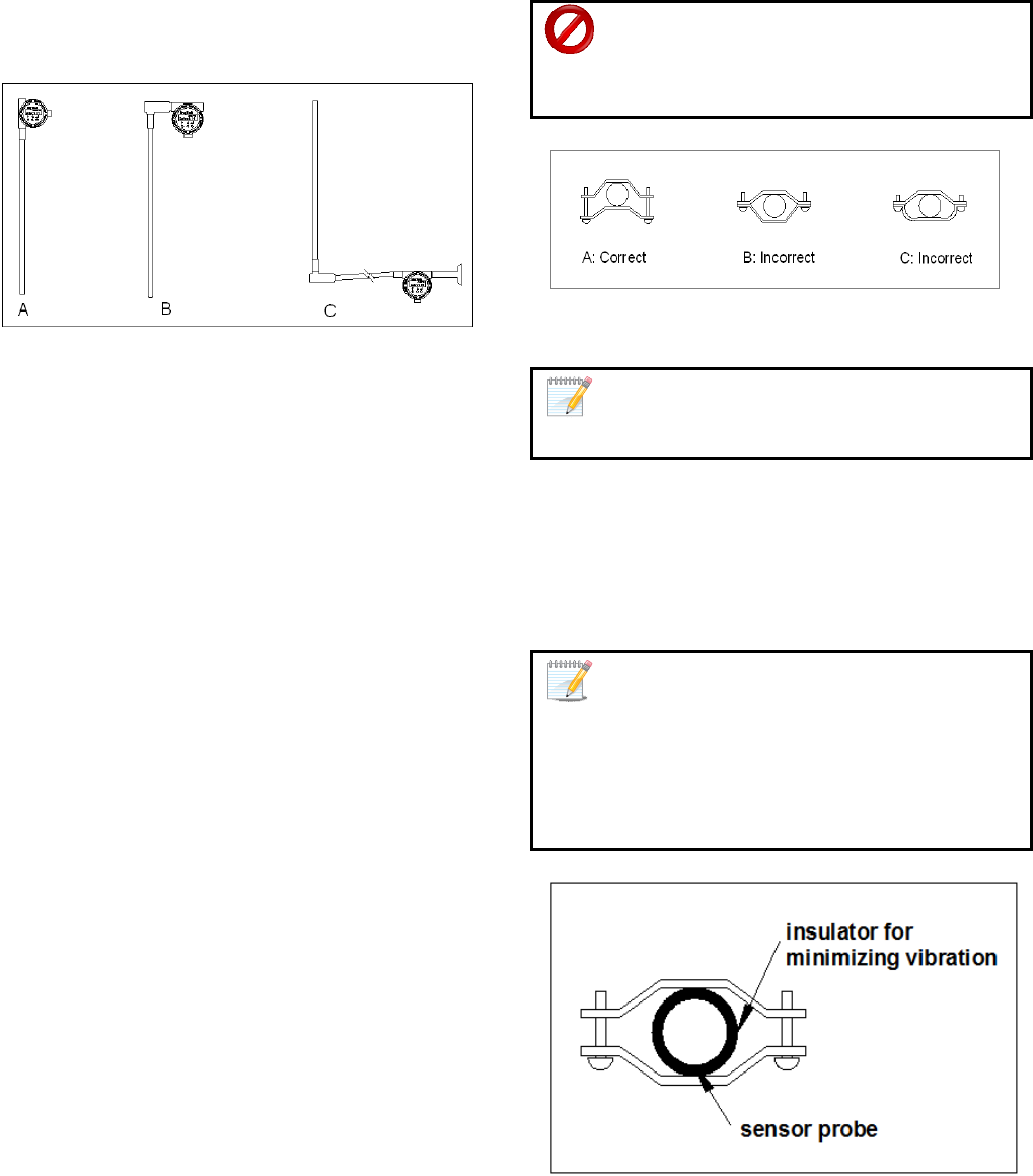
LTM Series transmitters, they are:
Figure 9. Possible transmitter configurations
Transmitter A is a standard top mount
configuration.
Transmitter B is a top mount with elbow, usually
utilized when there are temperature or head room
issues. There is also a bottom mount with elbow
configuration which is not depicted.
Transmitter C is a bottom mount transmitter with
remote electronics. This configuration is utilized in
more extreme temperatures or for accessibility.
There is also top mount with remote electronics
which is not depicted.
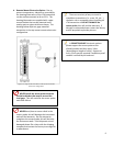
3. Mounting the Transmitter. Align the 4/20 mA
(or 0 and 100%) markings with the center of the
top and bottom process connection. Mount the
transmitter along the level gage and use a nut
driver to tighten the clamps so the sensor probe
of the transmitter is held securely (will not slip
up and down). Keep the transmitter supported
while the clamps are being tightened (this can
require more than one person).
Do not over tighten the clamps because
they will bend and distort.
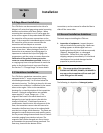
Figure 10. Top view of mounting clamps and sensor probe
A: Is the correct way to have clamps tightened.
The clamps do not have to meet.
B: Is incorrect because the clamp is flipped around
and will not grip the sensor probe.
C: Is incorrect because the clamp has been tighten
too much and damaged/distorted.
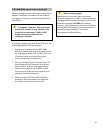
Effects of high vibration can be minimized
early on by notifying the factory at time of
order. The electronics can be remote mounted
and special insulators can be installed. Please
see the depiction below.
Figure 11. Insulator for high vibration
8