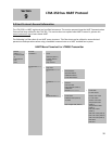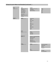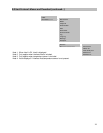
7.2 Features (Exclusive to the LTM-250/350 models)
Please consult factory before attempting this procedure. Document transmitter’s serial number for
better assistance.
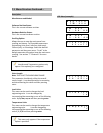
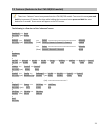
1-point Calibration Procedure (1pt Cal): The following menu is the 1 –point Calibration procedure.
This procedure was designed to help the user get up and running in an emergency. If electronics have to be
shared in an emergency the following procedure guides the user through a “quick” calibration procedure that
does not require level simulation but instead works with the current level (1 point) in the vessel/tank.
1. Enter into the “1pt Cal” menu by changing the “no” to a “yes” and pressing enter.
2. The first menu is “SelLngth” or select length.
This is not the measuring range but the overall probe
length. This information can be found on the label of the instrument housing. (See Section 2.1 Product
Identification). Enter the value in using the up or down arrows and press enter.
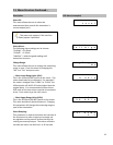
3. The second menu is “Sel LRV” or select lower range value. Most of the time this value is at 0.00in. It is
recommended to leave this value at zero and press enter.
4. The next menu is “Sel URV” or select upper range value. Enter in the desired measuring range and press
enter.
5. The “Energy” menu is next. This parameter controls the amount of energy being sent down the sensor
probe. Longer sensor probes require more energy shorter sensor probes require less energy. Please
contact the factory for guidance with this parameter.
6. The “DCOffset” menu is the signal to noise ration. Please contact the factory for guidance with this
parameter.
7. The “HoldTime” menu is the amount of time the energy being sent down the probe is sustained. Note:
a longer hold time can increase the deadband near the electronics. Please contact the factory for
guidance with this parameter.
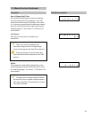
8. The last menu is the “CrntLvl” or current level menu. Enter the known current level in the vessel/tank
(in engineering units) and press enter. The calibration should take place and the transmitter should be
operational. If the next menu appears then the operation was successful. If the menu reverts back to
the beginning of the “1pt Cal” menu then the operation was unsuccessful. Further troubleshooting may
be necessary if the operation is unsuccessful. See
Section 8 for troubleshooting guide.
The 1-point calibration may not be within the published accuracy specification. Again this procedure
was designed to get a critical application up and running. A recalibration (two point calibration) may be
highly desirable as soon as the opportunity presents itself.
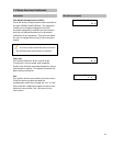
Level Adjustment (LvlAdjst): If the level gage indicator and level transmitter reading do not match or appear
to be incorrect by a few inches then the “LvlAdjst” function can be utilized. Enter into the menu and simply use
the up and down push buttons to enter the current level being displayed by the level gages visual indicator and
then press enter. The transmitter will adjust the calibration and output accordingly. Note: Be careful make sure
this is what is desired.
25


