


11
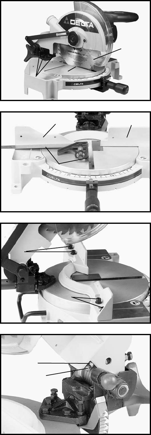
Fig. 21
Fig. 22
Fig. 23
Fig. 24
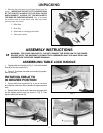
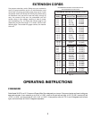
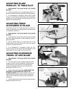
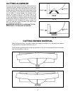
ADJUSTING BLADE
PARALLEL TO TABLE SLOT
1. DISCONNECT THE SAW FROM THE POWER
SOURCE.
2. Lower the cutting arm. The saw blade (A) Fig. 21,
should be parallel to the left edge (B) of the table opening.
3. If an adjustment is necessary, loosen three screws
(C) Fig. 21, and move the cutting arm until the blade is
parallel with the left edge (B) of the table opening. Then
tighten the three screws (C).
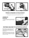
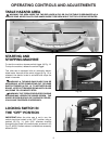
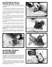
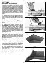
ADJUSTING FENCE
90 DEGREES TO BLADE
If the fence (A) Fig. 22, is ever removed from the saw it
should be adjusted so it is 90 degrees to the blade when
it is replaced, as follows:
1. DISCONNECT THE SAW FROM THE POWER
SOURCE.
2. This adjustment should be made only after the blade
has been adjusted parallel to table opening, as previ-
ously explained.
3. Using a square (B) Fig. 22, place one end of the
square against the fence (A) and the other end against
the slot in the table as shown.
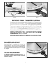
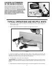
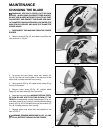
4. If an adjustment is necessary, loosen the four
screws (C) Fig. 23, and adjust fence 90 degrees to the
table opening. Then tighten the four screws (C).
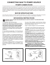
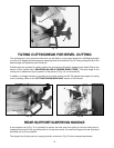
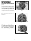
ADJUSTING DOWNWARD
TRAVEL OF SAW BLADE
1. DISCONNECT THE SAW FROM THE POWER
SOURCE.
2. The downward travel of the saw blade should be
limited to prevent the saw blade from contacting any
metal surfaces of the machine. This adjustment is
made by loosening locknut (A) Fig. 24, and turning
adjusting screw (B) in or out.
3. When making this adjustment, MAKE SURE THE
MACHINE IS DISCONNECTED FROM THE
POWER SOURCE and lower the blade as far as pos-
sible. Rotate the blade by hand to make certain the
teeth do not contact any metal surfaces and adjust if
necessary.
4. After the downward travel of the saw blade has been
adjusted, tighten locknut (A)
C
B
A
A
A
B
C
C
B
A