


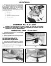
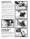

ADJUSTING 90 AND 45
DEGREE BEVEL STOPS
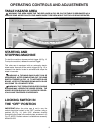
1. DISCONNECT THE SAW FROM THE POWER
SOURCE.
2. Loosen bevel lock handle and move the cutting arm
all the way to the right, then tighten the bevel lock handle.
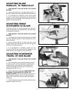
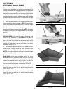
3. Using a square (A) Fig. 25, place one end of the
square on the table and the other end against the blade.
Check to see if the blade is at 90 degrees to the table,
as shown in Fig. 25.
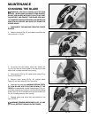
4. If an adjustment is necessary, loosen locknut (B)
Fig. 26, and turn screw (C) until head of screw (C) con-
tacts casting (D) when blade is 90 degrees to the table.
Then tighten locknut (B).
5. Loosen bevel lock handle and move the cutting arm
all the way to the left bevel position and tighten bevel
lock handle.
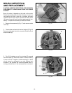
6. Using a combination square (A) Fig. 27, check to
see if the blade is at 45 degrees to the table, as shown.
12
Fig. 25
Fig. 26
Fig. 27 Fig. 28
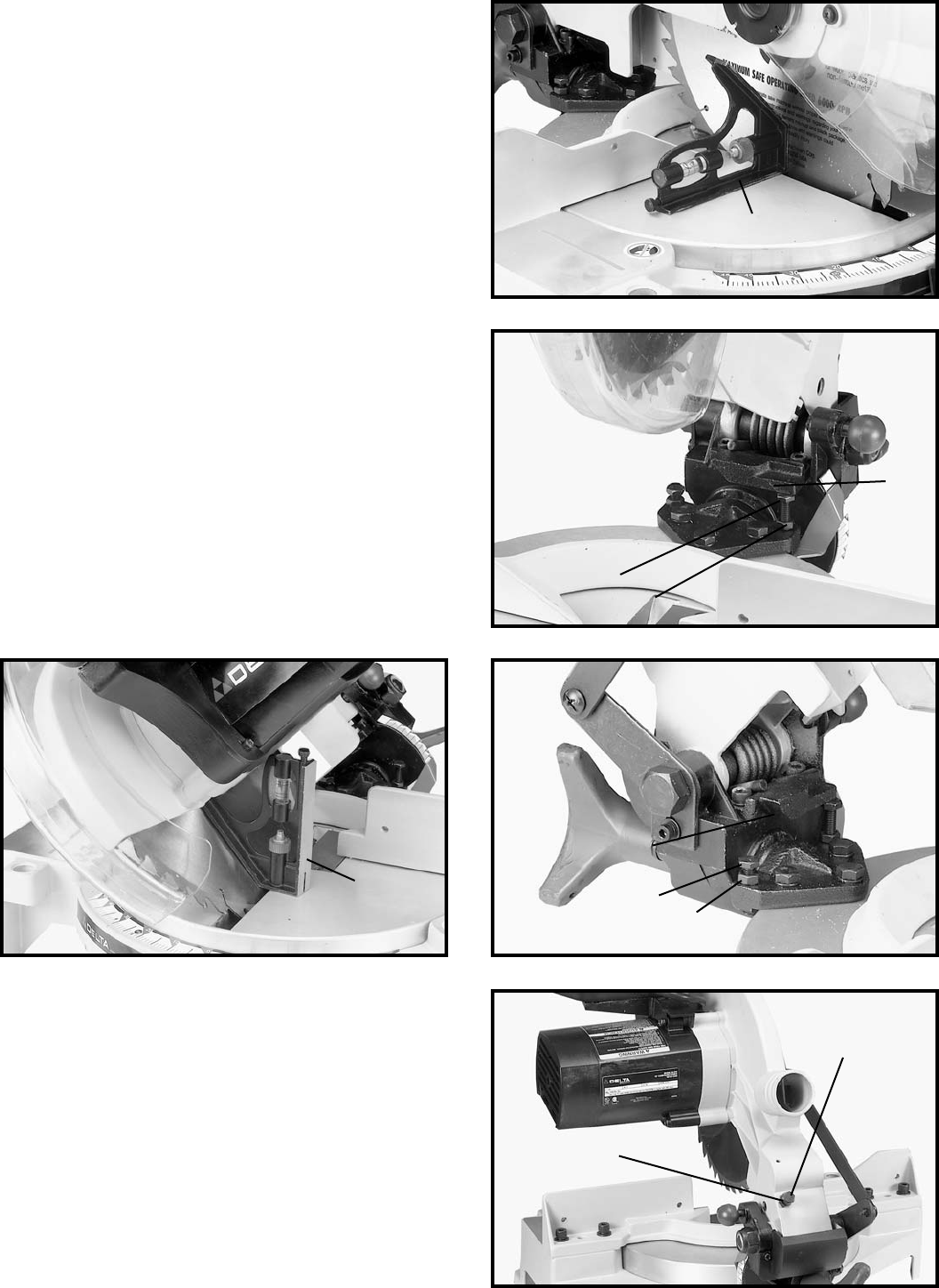
7. If an adjustment is necessary, loosen locknut (E)
Fig. 28, and turn screw (F) until screw (F) contacts casting
(G) when blade is 45 degrees to the table. Then tighten
locknut (E).
8. These positive stops enable you to rapidly position
the blade at the 90 and 45 degree bevel angle to the
table.
A
C
B
D
A
E
F
G
B
A
Fig. 28A
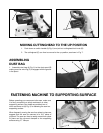
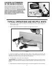
ADJUSTING TENSION
OF CUTTINGHEAD
RETURN SPRING
The tension of the cuttinghead return spring has been
adjusted at the factory so the cuttinghead returns to the
up position after a cut has been made. If it ever becomes
necessary to re-adjust the spring tension, proceed as fol-
lows:
1. Loosen locknut (A) Fig. 28A, and turn screw (B)
clockwise to increase or counterclockwise to decrease
the spring tension. After the spring tension has been
adjusted, tighten locknut (A).