


2
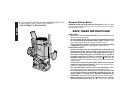
SERVICE
• Tool service must be performed only by qualified repair
personnel. Service or maintenance performed by unqualified
personnel could result in a risk of injury.
• When servicing a tool, use only identical replacement parts.
Follow instructions in the Maintenance section of this manual.
Use of unauthorized parts or failure to follow Maintenance
Instructions may create a risk of electric shock or injury.
Additional Safety Rules
• Hold tool by insulated gripping surfaces when performing an
operation where the cutting tool may contact hidden wiring or
its own cord. Contact with a “live” wire will make exposed metal
parts of the tool “live” and shock the operator.
• Keep handles dry, clean, free from oil and grease. It is
recommended to use rubber gloves. This will enable better control
of the tool.
•
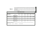
The label on your tool may include the following symbols.
• The label on your tool may include the following symbols.
V ............................volts
A ............................amperes
Hz ..........................hertz
W ..........................watts
min ........................minutes
..........................alternating current
......................direct current
n
o ..........................no load speed
..........................
Class II Construction
…/min ....................revolutions or reciprocation per minute
..........................earthing terminal
..........................safety alert symbol
Motor
Be sure your power supply agrees with nameplate marking.
120 AC means your tool may be operated only with alternating
current and never with direct current.
Voltage decrease of more than 10% will cause loss of power and
overheating. All tools are factory tested; if this tool does not operate,
check the power supply.
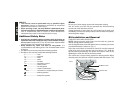
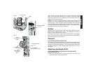
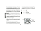
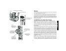
Bit Installation and Removal
TURN OFF AND UNPLUG ROUTER
NOTE: Always snap the collet firmly into the collet nut, (past the
retainer spring) before installing a bit.
Use the supplied wrench and the spindle lock as necessary to loosen
(counterclockwise) the collet nut, (Fig. 1).
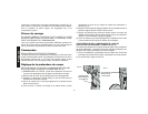
Insert the round shank of the desired router bit into the loosened
collet as far as it will go and then pull it out about 1/16". Hold the
spindle shaft by depressing the spindle lock button, while firmly
tightening the collet nut with the wrench provided.
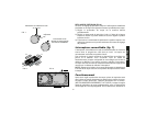
Your router has a unique locking system for retaining the bit. When
removing a bit, the collet nut must be loosened with the wrench. The
English
FIG. 1
SPINDLE LOCK
COLLET NUT