


HEIGHT SENSOR INSTALLATION (cont.)
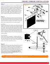
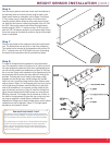
Step 6
Once the sensor positions have been found, mark the locations of
the mounting holes on the vehicle frame using the holes in the
height sensor bracket as a template, refer to Figure 3 and Figure
5. Use a center punch to mark the center of the holes on the
mounting surface. Before drilling the holes make sure all electri-
cal, brake and fuel lines are cleared from the path of the drill. Drill
two 3/16” holes on the center marks. Mount the height sensor
bracket using the 10-32 X 1” machine screws, 10-32 nylon lock
nuts and 3/16” flat washers located in your hardware pack. Ensure
that a clear access to the electrical contact on the top of the height
sensor is maintained.
Step 7
Place the axle bracket on the suspension below the height sensor
arm. This bracket does not have to be on top of the suspension.
This bracket can be mounted to the suspension with provided 10-
32 x 1” machine screw and 10-32 Nylon lock nut or by clamping
the bracket to the suspension with the provided hose clamp.
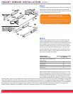
Step 8
To install the linkage from the suspension to the height sensor
arm. Put suspension at either full rebound or full jounce; mark off
link from suspension position ball joint and to corresponding sen-
sor link ball joint according to template as per Figure 3. That posi-
tion is now set. Slowly move suspension to the opposite end of its
travel ensuring that the sensor arm stays within the limits of the
template. The parts that you will need for the linkage are M5
threaded rod, two M5 jam nuts, two M5 linkages and two M5
Nylon lock nuts. Layout the linkage with the same distance meas-
ured as shown in Figure 3. If the threaded rod is too long it can be
cut to length using a hacksaw. Install the M5 jam nut over both
ends of the threaded rod, cut if needed, and then install the link-
ages on both ends as shown in Figure 6. Install the finished link-
age on the axle bracket and the height sensor arm using the two
M5 Nylon lock nuts. The linkages can be screwed up or down on
the shaft for fine adjustment to insure that you are not out of sen-
sor range as explained in Height Sensor Installation: Step 5.
Adjustment of linkage can be used to adjust sensor arm to achieve
centered arm travel as depicted in Figure 3. The height sensor
template can be removed if desired.
7
Figure 6
How much travel should I have?
The amount of travel is dependent upon the working range of the
height sensor arm and linkages. The system will perform if the sen-
sor arm operates within the yellow section of the sensor template.
The height sensor arm needs to be in the specified working range
(yellow area of the template) throughout the entire suspension
travel, not only through the travel for the selected lowered and
raised heights. Allowing travel outside of this working range will
result in a system fault.