


C
C
ongratulations on your purchase of a new IntelliRide system by Firestone. This kit will provide automatic height control and leveling of
your vehicle. The following will introduce you to the system components as well as provide detailed instructions concerning installing the
height sensors and programming the system. Be sure to take all applicable safety precautions during the installation of this kit. Position
the vehicle on a solid level surface and apply the parking brake. Disconnect the negative battery cable from the battery. With the vehicle on a solid,
level surface raise the vehicle and remove the wheels. After the removal of the wheels, lower the vehicle so the suspension rests on jack stands
rated for your vehicle's weight.
TOOLS REQUIRED
> Drill > 1/2” End wrench > Phillips head screw driver
> 3/8” Drill bit > 10mm End wrench > Sharp knife
> 3/16” Drill bit > 8mm End wrench > Pliers
> Center punch > 7mm End wrench > Tape measure
> Hacksaw > 3/8” End wrench > Marker
> 1” Hole saw > 9/16” End wrench
PARTS LIST
ii
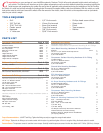
Top Box Components Part # Qty
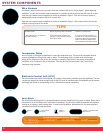
Valve block 9235 1
Pressure Sensor 0002 1
1/4 NPT Straight Fittings 3100 8
Air Compressor 9210 1
Electronic Control Unit 0200 1
Air Dryer 0004 1
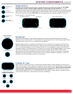
Height Sensors 0100 4
Height Sensor Bracket 5342 4
Height Control Rod 3265 4
Height Sensor Template 8252 4
Bottom Layer Components Part # Qty
Air Tank, 3 Gallon 9127 1
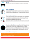
Wire Harness & Connections Part # Qty
Variable Leveling Connection (Park Wire) 0008 1
Wire Harness With Switches, Grommet 9238 1
Hardware & Tubing Part # Qty
Separate Plastic Bag with:
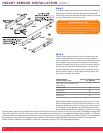
Hardware Required for Height Sensor Installation (Figure 2)
10-32 x 1” Machine Screw 8
10-32 Nylon Lock Nut 8
3/16” Flat Washer 8
M5 x 8 mm Machine Screw 8
M6 x 16 mm Machine Screw 4
M6 Nylon Lock Nut 4
Height Control Arm 4
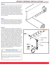
Hardware Required for Height Sensor Linkage Installation (Refer to
Figure 6)
Hose Clamp 4
Axle Mounting Bracket 4
Height Control Linkage 8
M5 Nylon Lock Nuts 8
M5 Jam Nut 8
1/4” Tubing, 18ft. 1
Hardware & Tubing Part # Qty
Separate Plastic Bag with:
Hardware Required for Component Mounting & Air Fittings
Valve Block Mounting Hardware & Exhaust Silencer
Silencer 3271 1
10-32 x 1-3/4” Socket Head Cap Screw 2
10-32 Nylon Lock Nut 2
3/16” Flat Washer 2
Compressor Isolator Mounting Hardware & Air Fitting
1/8 NPT Fitting 1
10-32 x 1” Machine Screw 3
10-32 Nylon Lock Nut 3
3/16” Flat Washer 6
Ground Wire Mounting Hardware
1
0-32 x 1” Machine Screw 1
10-32 Nylon Lock Nut 1
3/16” Flat Washer 1
ECU Mounting Hardware
10-32 x 1” Machine Screw 1
10-32 Nylon Lock Nut 1
3/16” Flat Washer 1
Air Dryer Mounting Hardware and Air Fittings
3/8 NPT Straight Fitting 2
10-32 x 1” Machine Screw 4
10-32 Nylon Lock Nut 4
3/16” Flat Washer 4
Compressor Relay Mounting Hardware
10-32 x 1” Machine Screw 1
10-32 Nylon Lock Nut 1
3/16” Flat Washer 1
Reservoir Mounting Hardware & Air Fittings
3/8” – 16 Flange Lock Nut 4
3/8” Flat Washer 4
3/8” – 16 x 1” Hex Head Bolt 4
1/4” NPT Plug 1
1/4” NPT Fitting 1
Tie Wraps to Securely Mount Wire Harness 30
Thermal Sleeves to Protect Tubing 4
Inflation Valve for Height Sensor Installation 4
(Air Spring Method)
Torque Recommendations - 1/4 NPT Tank Plug: Tighten the fitting securely to engage the orange thread sealant.
NPT Fittings: Tighten the air fitting so as to make contact with the nylon ring and then tighten 1/4 turn to snug the fitting. No thread sealant is needed.
Pressure Sensor: The pressure sensor is sensitive to over-torque. Carefully install the pressure sensor into the valve block with 7.2 ft-lbs. (9.8 N-m) of torque.