


5
HEIGHT SENSOR INSTALLATION
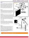
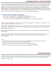
Step 1
There will be a bag in your kit with all of the hardware that you will
need to put the height sensors on your vehicle. Group a height
sensor from the kit with a height sensor bracket and two M5 x
8mm machine screws as indicated in Figure 2. Attach the bracket
and height sensor template to the sensor using the machine
screws, as shown in Figure 2. Next group a sensor arm and one
M6 x 16mm and one M6 lock nut. Attach the metal arm to the
sensor arm with the M6 x 16mm and the M6 lock nut, refer to
Figure 2. Repeat this procedure for the three other sensors.
Step 2
In the process of installing the height sensors the vehicle suspen-
sion must be able to go though the entire suspension movement,
with damper attached, from full jounce to full rebound to mechani-
cally prove height sensor position, refer to Figure 3. This can be
done by either using jack method or the air spring method.
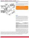
Jack Method
Raise the vehicle using a lift or platform jack rated for your vehicle
weight. Do not use wood or concrete blocks to support the weight
of the vehicle. Lower the vehicle frame onto jack stands rated for
your vehicle’s weight making sure the suspension is fully extended
to damper limit. Then to determine the jounce suspension position
that you will need to mount the height sensors, just jack the sus-
pension up to that point into the jounce stop. Make sure that the
air line is removed and that there is no air in the air springs when
using this method.
Air Spring Method
Cut four sections of air line tubing 3” in length and insert into
each air spring. Install the four inflation valves
(included with sys-
tem)
in the end of each hose. Now you can inflate and deflate the
air springs on suspension to find the location to mount the height
sensors. This will also make calibration easier.
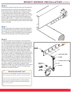
Step 3
Avoid direct heat from the engine and exhaust pipe when installing
height sensors. The height sensor linkage to the suspension
should be as close to 90° from sensor arm at ride height as possi-
ble. The sensor arm and sensor linkage should not be inline
throughout the entire travel of the height sensor linkage, from full
jounce to full rebound. An incorrectly mounted height sensor will
result in system not functioning. The height sensor must be
mounted with the electrical connection pointing up and the arm
in the correct position on the sensor.
Note: The best description of a poorly mounted height sensor is shown in Figure 3. Too big of an angle between the height
sensor arm and link may allow the arm to “toggle” over center.
Figure 2