


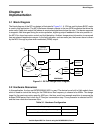

Commutation
Variable Speed DC Fan Control using the MC9RS08KA2, Rev. 0
Freescale Semiconductor 11
Chapter 2
Motor Control
2.1 Commutation
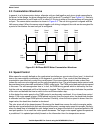
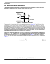
The typical bi-phase BLDC has one pole-pair per phase. Each commutation rotates the rotor by 90
degrees and four commutation steps complete a mechanical revolution. Each pole-pair is implemented
by two coils, with four coils in total for a bi-phase motor. Energizing a pair of coils, either coil A & C or coil
B & D as shown in Figure 2-1, induces magnetic fields that push the equal polarity rotor magnets away
from the energized coils and at the same time the opposite polarity rotor magnets are pulled toward the
coils. Rotation starts and this is called a commutation step. When the rotor magnetic pole is aligned with
the energized coils, the coils are deactivated and the previously un-energized pair of coils are then
energized. As the magnetic field switches to the next motor position or pole, the inertia of the rotor keeps
the motor running. As a result, two commutation steps moves the rotor by 180 degrees or one motor
phase. One mechanical revolution is contributed by four commutation steps.
To avoid conflict to the magnetic field, adjacent coils cannot be energized at the same time. Dead-time,
where all coils are un-energized must be added between each commutation step.
Figure 2-1. Bi-phase BLDC Motor Schematic
2.2 Rotor Position Control
The key idea to prevent a motor lockup concerns rotor position detection. The time to switch the
commutation is critical. Energizing coil-pair for too long will kill the rotor inertia and the motor stops
running. This is called motor lockup. Switching the commutation too soon will lose control to the rotor and
eventually stall the motor. The rotor position in this design is determined by a hall sensor which will
respond to the change in magnetic field. Hall sensor output toggles when the magnetic field changes its
polarity. Positioning the hall sensor between the coils at 45 degree to the stator coils, as shown in
Figure 2-1, can effectively detect the rotor position. In this case the hall sensor output toggles when the
rotor magnets is aligned to the coils. Commutation should switch at this time from one coil-pair to the next
coil-pair.
N
S
S
N
L1
L1
L2
L2
HALL
Coil A
Coil C
Coil B
Coil D