


Motor Startup
Variable Speed DC Fan Control using the MC9RS08KA2, Rev. 0
Freescale Semiconductor 13
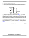
Dramatic changes in the dead-time value will cause the motor to stall. In this design a software loop in the
MCU will control the dead-time variation. Even with the dramatic change in the temperature sensor
reading, the software loop will only allow the dead-time to change to the new value gradually.
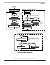
2.5 Motor Startup
In this DC fan application, it is desirable to only allow the motor to operate in an uni-direction, such that
the airflow to the target system will always be in one direction. With the bi-phase motor design it is difficult
to guarantee the direction of rotation. Commutation order or the coil energizing sequence happens to be
the same for both directions of rotation. The rotor position or axis must initially be known in order to
guarantee the direction of rotation. When the first commutation step is activated where the adjacent
coil-pair to the initial axis is energized, the rotor starts to move. Since the adjacent coil-pairs are
connected together and energized at the same time, there are equal pulling/pushing force induced on the
rotor in both directions. There is chance for the rotor to startup in either direction. It is necessary to monitor
the initial direction of rotation. If the direction is not correct, the motor must be locked back to the startup
axis again and the commutation step repeated. The direction of rotation can be detected by the Hall
sensor output. If the initial rotor axis is known, the output edge polarity, rising edge or falling edge,
determines the direction of rotation.
In the modern bi-phase motor design the direction of rotation is normally defined by the manufacturer. The
stator design is not symmetric such that the motor will have a high tendency to rotate in one direction than
the other. However, the direction of rotation cannot be guaranteed without proper monitoring techniques
in place.
2.6 Fault Detection
Motor fault is identified as the rotor not moving, which is normally the case when the rotor is jammed (may
be cause by blocked airflow). During each commutation step, the Hall sensor output is monitored. If it is
not toggled within a defined duration, commutation sequence is terminated, all coils are de-energized. In
this design, when a motor fault occurs, a buzzer is activated as the alarm.