


Implementation
Variable Speed DC Fan Control using the MC9RS08KA2, Rev. 0
16 Freescale Semiconductor
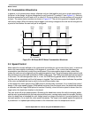
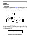
Hall sensor output is connected to the MCU’s GPIO port, PTA2, which has a programmable edge trigger
keyboard interrupt (KBI). The programmable edge trigger feature provides an effective way to monitor the
Hall sensor signal. As mentioned in the previous section, the direction of rotation can be detected by the
polarity of the Hall sensor output edge. Monitoring the signal edge is achieved by altering the KBI edge
trigger polarity for each commutation step.
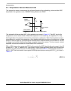
Ambient temperature reading is taken from a temperature sensor which is equivalent to a diode.
Temperature variation alters the diode channel current as well as the effective channel resistance. The
temperature sensor is combined with a 7.5kΩ resistor in a potential divider arrangement. The built-in
analog comparator is used to compare the temperature sensor ladder voltage with an defined RC network
to deduce the absolute temperature.
As described in the previous section, the motor speed is controlled by varying the absolute dead-time.
This is updated every 128ms in the application. As in all RS08/S08 devices, the MC9RS08KA2 MCU has
a programmable real time interrupt (RTI) feature. In this case, it is used to notify the MCU to refresh the
target PWM period every 128ms.
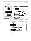
3.3 Control Loop
Figure 3-2 shows the firmware control loop flow chart. The KBI or Hall sensor output is continuously
monitored for trigger signals within a defined time. A motor fault condition occurs when there are no trigger
signal, and the firmware goes into a forever loop. Commutation is stopped and the buzzer is alarmed.
The target PWM period based on the temperature sensor reading is updated every 128ms. And on each
180 degrees rotation of the rotor (two commutation steps) the actual PWM period is compared with the
target PWM period. If they are different, the absolute dead-time will be altered, and the actual PWM period
will gradually change towards the target PWM period.
On each commutation step, reading of the temperature sensor contributes a delay to the actual dead-time
duration. This delay is deterministic such that the software control loop can easily deduce the actual
speed of the motor. Hence, this delay can be considered as a part of the total dead-time delay for each
commutation.