


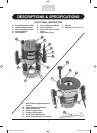

13
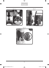
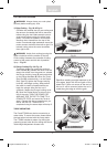
adjustments quickly. The icro Adjustment
knob (C) allows for fine adjustment of the
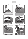
Turret Stop Rod. You can set three different
depths of cut for the same bit using the Turret
and stops –Fig 11. Adjust the height of the
three stop screws as necessary so that the
difference in height is equal to the amount of
material to be removed with each cut.
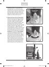
3) Setting the Router to Zero Plunge Depth:
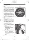
Rotate the turret (I) so that stop 3 is directly
under the Turret stop Rod – Fig 12. Loosen
turret stop rod locking screw (H) and raise
turret stop rod (D) to its highest position
using the course Adjustment Knob (F) – Fig
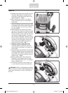
13. Release plunge locking lever (P) and
gently plunge the router motor until the router
bit barely touches the work surface. Lock the
plunge locking lever – Fig 14. Rotate the
coarse adjustment knob (F) to move the turret
rod downward until it contacts stop 3. Raise
the Turret Stop Rod until the arrow indicator
is aligned with the closest large increment on
the scale (i.e.,
1
⁄4",
1
⁄2",
3
⁄4", 1", etc.) – Fig 15.
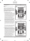
Turn the micro adjustment knob (C) until the
turret stop rod contacts the stop screw.
Tighten the stop rod locking screw – Fig 16.
Your router is now set to zero plunge depth.
Release the plunge locking level to allow the
router’s motor to return to its maximum
height. To adjust the router to your required
cutting depth, rotate the coarse Adjustment
screw to raise the Turret Stop Rod until the
measurement on the scale is equal to the
amount required for your final depth of cut.
English
Fig. 11
3 Turret Stop
Positions:
1
2
3
Fig. 12
Fig. 13
H
D
X
English FT3000 Manual.indd 13English FT3000 Manual.indd 13 10/18/06 11:57:53 AM10/18/06 11:57:53 AM