


Using the Dual 28V Input Voltage Charger with Linear Regulator, Rev. 1.0
10 Freescale Semiconductor
Evaluation Board Configuration
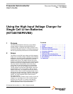
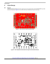
7.2 Connector Pads
There are 14 connecting pads (TP1 to TP14 with corresponding names) on the evaluation board to let the user simply
connect the board to their system. The GND pads link power ground of the MC34676B. The AC pad or USB pad connect
an external power source to the evaluation board. The
PPR, CHG, USBEN, BATDET, USBOUT, ISET, IUSB and the
IMIN pads link to the corresponding pins of the MC34676B. The VL pad is for the user to supply a logic I/O voltage to
the evaluation board, if that application system needs a logic voltage level to interface to the PPR and CHG pins of the
MC34676B. The VBAT pad connects the positive pole of the Li+ battery being charged.
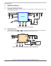
7.3 Test Points
The KIT34676EPEVBE evaluation board provides 11 signal test points and 3 ground test points for users to conveniently
hook up multi-meters and oscilloscope probes to evaluate the MC34676B. The test points connect the pins of the
MC34676B with the same names directly.
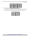
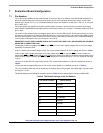
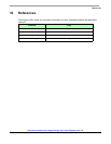
J11 Open
J12 Shorted
J13 Open
Table 4. The Default Settings of the Pin Headers