


Using the Dual 28V Input Voltage Charger with Linear Regulator, Rev. 1.0
Freescale Semiconductor 9
Evaluation Board Configuration
7 Evaluation Board Configuration
7.1 Pin Headers
The J1 and J3 pin headers link the external power source to the AC pin or USB pin of the MC34676B respectively. It
allows the user to measure the current from the power source to the evaluation board when using a current meter
between pin 1 and pin 2 of J1 or J3. The default setting of the two pin headers is to short pins 1 and 2 of J1, and open
pins 1 and 2 of J3.
The J2 pin header links the BAT pin and the external battery connector. It allows the user to measure the charging
current from the MC34676B into the battery with a current meter between pin 1 and pin 2. The default setting is to short
pins 1 and 2.
The J4 and J5 pin headers select the voltage to supply the D1 and D2 LED indicator. Shorting pins 2 and 3 of J4 and
pins 2 and 3 of J5 select AC to power the LEDs. Shorting pins 1 and 2 of J4 and pins 2 and 3 of J5 select USB to power
the LEDs. Shorting pins 1 and 2 of J5 and let all pins of J4 open select BAT to power the LEDs. The default settings of
J4 and J5 are to short pins 2 and 3 of J4 and pins 2 and 3 of J5.
IMPORTANT: DO NOT APPLY HIGHER THAN A 12V DC INPUT VOLTAGE TO AC OR USB WHEN AC OR USB IS
SELECTED TO POWER THE LEDS.
The absolute maximum voltage at the PPR pin and CHG pin is 12V. When applying higher than a 12V input voltage,
select BAT to power the LEDs.
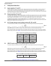
J6 and J7 set the AC CC-mode charge current. The current values related to J6 and J7 settings are shown in Table 1.
J8 and J9 are used to let the user supply an I/O logic voltage to the PPR pin and the CHG pin, so the system can
interface the PPR and CHG signals with the same voltage level. When using LEDs to indicate the charging status, leave
J8 and J9 open. When interfacing the PPR and CHG signals to the system, short pins 1 and 2 of J8 and J9 and leave
J5 open.
J10 and J11 set the USB CC-mode charge current. The current values related to J10 and J11 settings are shown in
Table 2.
J12 sets the end-of-charge (EOC) current. The current values related to J12 settings are shown in Table 3.
The J13 pin header allows the user to choose the AC charger when leaving it open, the USB charger is chosen when
shorting pins 1 and 2.
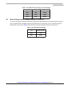
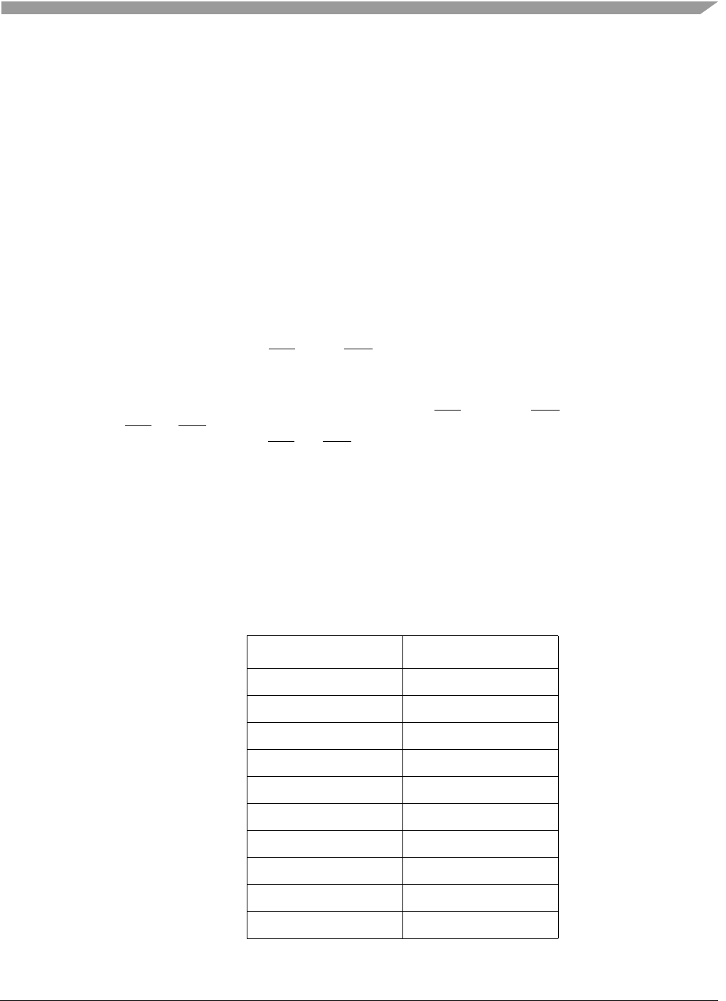
The default settings of the evaluation board are shown in Table 4, which selects the AC charger of MC34676B.
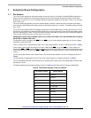
Table 4. The Default Settings of the Pin Headers
Pin Header Jumpers Default Setting
J1 Shorted
J2 Shorted
J3 Open
J4 2-3 shorted
J5 2-3 shorted
J6 Shorted
J7 Shorted
J8 Open
J9 Open
J10 Open