


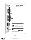

6KBU300
—————— TECHNICAL DATA ——————
3
3
3.2. HARDWARE SPECIFICATIONS
3.2.1. Power required
The supply of the braking unit is directly obtained by the DC Link and the maximum consumption is 15W.
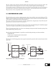
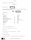
3.2.2. Internal fuses
Denomination Protection for Fuses
F1 Switching input supply 4A 500V slow 6 x 32 mm
F2 +24V supply (terminals 1 and 2) 315mA 250V slow 5 x 20 mm
Master output command (terminals 5 and 6)
F3 Supply of the internal fan (+24V) 1A 250V slow 5 x 20 mm
bu0015
The fuse F2 for the +24V supply (terminals 1 and 2) and Master output command (terminals 5 and 6) is mounted
on the front panel.
Replacement vendor sources:
Fuse 1 - Omega (Europe) GF632240
Fuse 2 - Omega (Europe) ST520131
- Littlefuse 218315
Fuse 3 - Omega (Europe) ST520210
- Littlefuse 218001
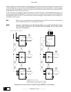
3.2.3. Signalling LEDs
Denomination Colour Function
24 V green It shows presence of the power supply
MASTER yellow The braking unit is set as master
BR yellow The braking unit is active (braking)
OK green OK relay status (closed = OK)
AL red It shows the alarm condition
bu0020
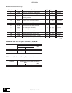
3.2.4. Terminal strip
The power terminal strip is composed by the following terminals:
Terminals Function I/Q Volt. max. Curr. max.
C
Connection to the intermediate circuit of the
inverter
I 770Vdc I peak
D
Connection to the intermediate circuit of the
inverter
I 770Vdc I peak
CR Connection to the braking resistor Q 745V dc I peak
BR Connection to the braking resistor Q 745V dc I peak
PE Ground connection – – –
bu0025