


GEI-100350A
—————— TECHNICAL DATA ——————
3
4
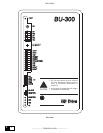
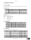
Regulation board terminal strips:
Terminals Name Function I/Q Volt. max. Curr. max.
1 +24V Supply for commands TIM-RESET Q 24V 200mA
2 0V 24V 0V potential of the +24V supply – –
3 TIM
Connection for the thermal contact of
resistor protection
I 15...30V 3.2...6.4 mA
4 RESET Remote Reset of alarm condition I 15...30V 3.2...6.4 mA
5 MCMD Slave unit command (Master output) Q 24V ± 5% 30 mA
6 0V 24V 0V potential of MCMD command – –
7 SIN Slave unit input command I 8...30V 16 mA
8 SIN Slave unit input command I 8...30V 16 mA
9 SOUT Cascade connection of Slave units Q 8...30V 16 mA
10 SOUT Cascade connection of Slave units Q 8...30V 16 mA
75 OK OK relay dry contact (closed = OK) Q 250Vca 1 A
76 OK OK relay dry contact (closed = OK) Q 250Vca 1 A
bu0030
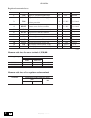
Maximum cable sizes for power terminals C,D,CR,BR
Braking Unit type Maximum Permissible Cable Cross-Section
[mm
2
]
flexible multi-core
6KBU300-20 10 10 12
6KBU300-50 16 16 10
6KBU300-85 35 35 2
bu0031
AWG
Maximum cable sizes of the regulation section terminals
Terminals Maximum Permissible Cable Cross-Section
[mm
2
]
flexible multi-core
1 ... 76 0.35 ... 1.5 0.35 ... 1.5 22 ... 16
bu0032
AWG