


6KBU300
—————— TECHNICAL DATA ——————
3
5
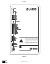
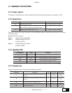
3.2.5. Dip Switches description
Denomination Function
S1-1
Enabling of the function for quick discharge of the DC link
Standard = OFF
S1-2 ... S1-5
Selection of intervention threshold of the braking unit
Braking threshold S1-2 S1-3 S1-4 S1-5
400V dc OFF OFF OFF ON
640V dc OFF OFF ON OFF
680V dc OFF ON OFF OFF
745V dc ON OFF OFF OFF
S1-6
Not used
S2
MASTER = Selection of braking unit function as Master (standard)
SLAVE = Selection of braking unit as Slave
S3
Button Reset of alarm condition
bu0035
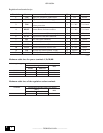
3.3. SELECTION OF THE INTERVENTION THRESHOLD
The DC threshold of the braking unit must be set accordingly to the supply voltage value of the connected
inverter, setting the switches as described in the following table.
NOTE: It is possible to select only one braking threshold at a time.
Voltage Braking threshold Position of the switches
supply [V
BR
] S1-2 S1-3 S1-4 S1-5
230Vac 400Vdc OFF OFF OFF ON
400Vac 680Vdc OFF ON OFF OFF
460Vac 745Vdc ON OFF OFF OFF
bu0010
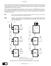
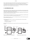
3.4. PARALLEL CONNECTION OF THE UNIT
There is the possibility to connect up to four braking units in parallel. For this purpose, terminals C and D must be
parallel connected and one of the units must be set as Master function, while the others as Slave (through switch
S2).
Only the Master needs to be selected for the desired intervention threshold (through switches S1-2...S1-5).
Connect the braking units as showed in the picture, paying particular attention to the correspondance of the
terminals connection C and D. For the cascade’s command connections (terminals 5 ... 10) correspondence of
terminals polarity is not requested, but it is advisable to use twisted cables.