


GEI-100350A
—————— DIMENSIONING... AND CORRESPONDING... ——————
4
4
4.1. SIMPLIFIED DIMENSIONING OF THE RESISTOR
In case all the above mentioned data were not available, it is possible to carry out the braking resistor calculation
in a simplest but approximately way.
This solution can lead to an overdimensioning of the resistor which has to be used.
For the calculation of different resistor values (to use e.g. with different threshold intervention values of the
braking unit) it is possible to use the following formula:
R[]=
BR
Ω
V [V]
BR
I [I]
PBU
f011
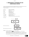
Where “V
BR
” means the intervention threshold of the braking unit and “IPBU” the max. peak current described
in the table.
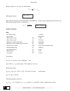
Needing to calculate the value of the resistor for an inverter 6KAV3037 (100A peak current for the braking)
supplied with 400V (intervention threshold 680V with S1-3 ON) we will have:
R=
BR
= 6,8 ohm
680
100
f012
This formula shows the ohmic value, while about the resistor power the following consideration have to be taken
into account.
The braking resistor is normally used with intermittent cycle; it will be possible in this way to use a resistor able to
dissipate a costant power lower than the one given by the product R
BR
* I
PBR
2
.
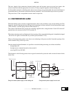
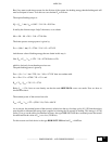
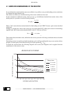
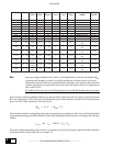
To decide the overload factor the following diagram can be used (such diagrams can be supplied from the
manufacturer of the resistor to use).
1000
100
10
1
0,1
1
3
45
6
7
89
10
RESISTANCE POWER
2
OVERLOAD FACTOR
OVERLOAD TIME (seconds - log. Scale)
Pause time
15 seconds
30 seconds
1 minute
5 minutes
30 minutes