


10
the mitre table to the desired position. The mitre table
features positive click stops for quick setting of common
mitre angles.
WARNING. Be sure to tighten the mitre table locks before
making a cut. Failure to do so could result in the table
moving during the cut and cause serious personal injury.
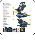
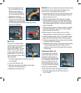
Bevel lock
The bevel lock (12) is used to set
the blade at the desired bevel
angle (fig. H). The mitre saw bevel
cuts from 0° to 45° to the left. To
adjust the bevel angle loosen the
bevel lock and adjust the saw arm
to the desired bevel angle.
WARNING. Be sure to tighten
the bevel lock before making
a cut. Failure to do so could result in the saw arm moving
during the cut and cause serious personal injury.
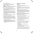
Spindle lock button
The spindle lock button (25)
prevents the blade in the saw
from rotating (fig. I). Depress and
hold the spindle lock button while
installing, changing, or removing
the blade.
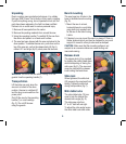
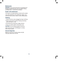
Rotating lower
blade guard
The rotating lower blade guard
(9) provides protection from both
sides of the blade. It retracts
over the upper blade guard (8)
as the saw is lowered into the
workpiece workpiece (fig. J).
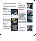
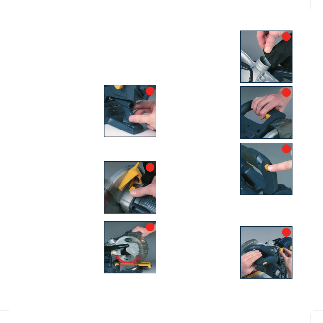
Dust bag
The dust bag (28) fits over the
dust extraction port (27) (fig. K).
For more efficient operation,
empty the dust bag when it is no
more than half full. This allows
better air flow through the bag.
Turning on and off
1. To turn the saw on depress
and hold the on/off trigger
switch (23) (fig. L).
2. To turn the saw off release the
on/off trigger switch (23).
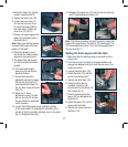
Turning on the REDEYE
®
laser line generator
The REDEYE
®
laser line
generator emits an intense
narrow beam of pure red light to
guide you as you cut. It improves
operator cutting vision, enables
faster set-up, increases accuracy
and improves safety. To turn on
the laser line press the laser light
on/off switch (2) (fig. M). To turn off the laser press the laser
light on/off switch (2) one more time.
Setting the table square with the blade
1. Make sure that the electrical
plug is removed from the
power point.
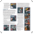
2. Push the saw arm (5) down
to its lowest position and
engage the release knob (6)
to hold the saw arm in the
transport position (fig. N).
3. Loosen the mitre locks (18).
H
I
J
K
L
M
N