


9
Unpacking
Due to modern mass production techniques, it is unlikely
that your GMC Power Tool is faulty or that a part is missing.
If you find anything wrong, do not operate the tool until the
parts have been replaced or the fault has been rectified.
Failure to do so could result in serious personal injury.
1. Remove all loose parts from the carton.
2. Remove the packing materials from around the saw.
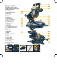
3. Using the operating handle (7) carefully lift the saw from
the carton and place it on a level work surface.
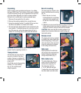
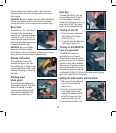
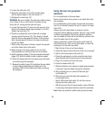
4. The saw has been shipped with the saw arm locked in the
down position. To release the saw arm, push down on the
top of the saw arm, pull on the release knob (6) (fig. A),
rotate it 45° and let go (fig. B), slowly raise the saw arm.
A
B
WARNING. Do not lift the saw whilst holding on to the
guards. Use the operating handle (7).
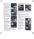
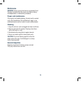
Transportation
Lift the mitre saw only when the
saw arm is locked in the down
position, the saw is switched off
and the plug is removed from the
power point.
Only lift the saw by the operating
handle (7) or outer castings
(fig. C). Do not lift the saw
using the guards.
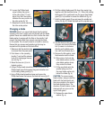
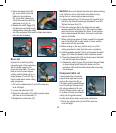
Bench mounting
The saw base has 5 holes in the
base to facilitate bench mounting
(fig. D).
1. Mount the saw to a level,
horizontal bench or work table
using bolts (not supplied) and
fix the saw to the bench using
5 bolts.
2. If desired, you can mount the saw to a piece of 13mm or
thicker plywood which can then be clamped to your work
support or moved to other job sites and re-clamped.
CAUTION. Make sure that the mounting surface is not
warped as an uneven surface can cause binding and
inaccurate sawing.
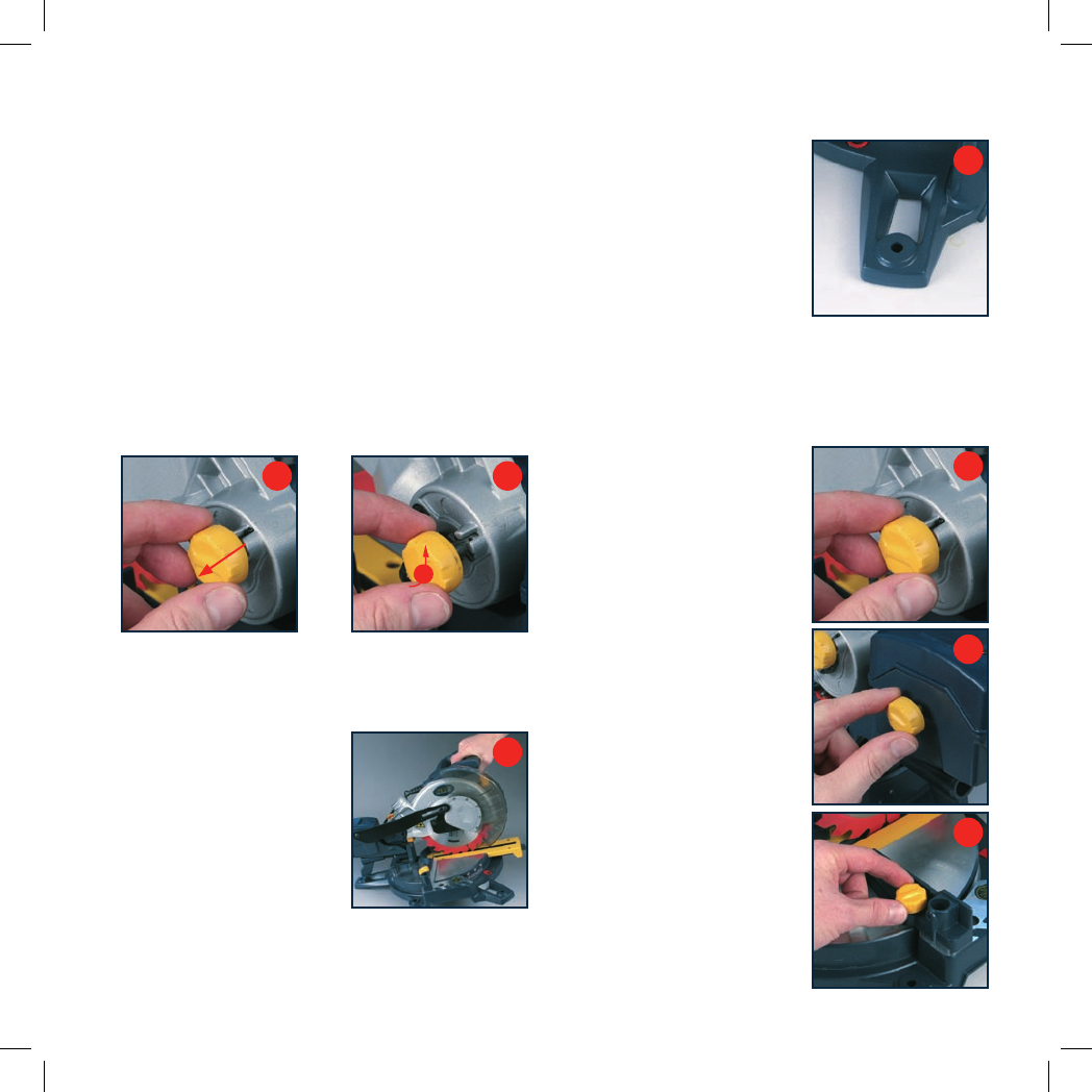
Release knob
The release knob (6) is provided
for holding the cutting head down
whilst transporting or storing the
mitre saw (fig. E). The saw must
never be used with the release
knob locking the head down.
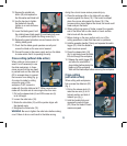
Slide lock
When tightened, the slide lock
(22) prevents the saw head from
sliding. Tighten the slide lock
during transportation (fig. F).
Mitre table locks
The mitre table locks (18) are
used to lock the table at the
desired mitre angle (fig. G).
The mitre saw cuts from
0° to 45° both left and right.
To adjust the mitre angle loosen
the mitre table locks and rotate
C
D
E
F
G