


12
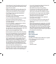
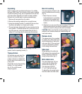
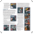
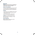
10. Loosen the Phillips head
screw holding the pointer
of the mitre scale (17) and
adjust it so that it accurately
indicates the zero position on
the mitre scale (fig. W).
11. Retighten the screw securing
the mitre scale pointer.
Changing a blade
DANGER! Never try to use a blade larger than the stated
capacity of the saw. It might come into contact with the blade
guards. Never use a blade that is too thick to allow the outer
blade washer to engage with the flats on the spindle. It will
prevent the blade screw from properly securing the blade
on the spindle. Do not use the saw to cut metal or masonry.
Ensure that any spacers and spindle rings that may be
required suit the spindle and the blade fitted.
1. Make sure that the electrical plug
is removed from the power point.
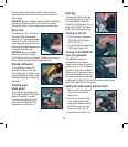
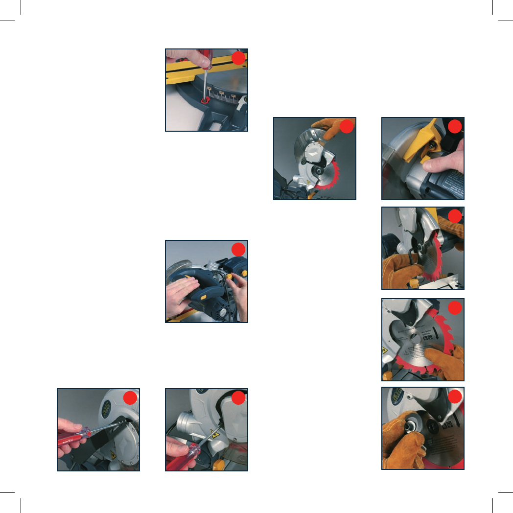
2. Push down on the operating
handle (7) and pull the release
knob (6) to disengage the saw
arm (5) (fig. X).
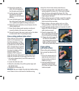
3. Raise the saw arm (5) to its
highest position.
4. Using a Phillips head screwdriver loosen and remove the
Phillips head screw that secures the guard retraction arm
to the rotating blade guard
(fig. Y)
.
5. Using a Phillips head screwdriver loosen and remove the
Phillips head screw that secures the blade bolt cover (fig. Z).
Y
Z
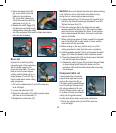
6. Pull the rotating blade guard (9) down then swing it up
together with the blade bolt cover (11). When the rotating
blade guard (9) is positioned over the upper fixed blade
guard (8) it is possible to access the blade bolt (fig. a).
7. Hold the rotating guard (9) up and press the spindle lock
button (25) (fig. b). Rotate the blade until the spindle locks.
a
b
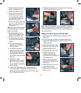
8. Use the 6mm hex key provided
to loosen and remove the blade
bolt. (Loosen in a clockwise
direction as the blade screw
has a left hand thread) (fig. c).
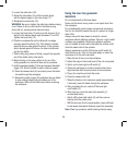
9. Remove the flat washer, outer
blade washer and the blade.
10. Wipe a drop of oil onto the
inner blade washer and the
outer blade washer where
they contact the blade.
11. Fit the new blade onto the
spindle taking care that
the inner blade washer sits
behind the blade (fig. d).
CAUTION. To ensure correct
blade rotation, always install the
blade with the blade teeth and
the arrow printed on the side of
the blade pointing down. The
direction of blade rotation is also
stamped with an arrow on the
upper blade guard.
12. Replace the outer blade
washer (fig. e).
W
X
c
d
e