


17309377
Service
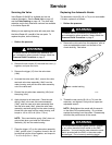
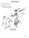
Servicing th e Valve
Valve Repair Kit 240453 is available and c an be
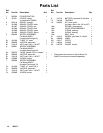
ordered separately. See the Parts List on page 18
and the P arts Drawing on page 19. The parts with
asterisks next to their reference numbers are available
in the Valve Repair Kit.
When you a re r epairing the valve with new parts from
the Valve Repair Kit, use all of the new parts. To
replace the parts, do the following:
1. Relieve the pressure.
WARNING
To reduce the risk of s erious injury whenev er y ou
are instructed to relieve pr essure, always follow the
Pressure Relief Procedure on page 5.
2. Remove the six screws (21) that hold the c over (1)
together, and open the cover.
3. Remove the trigger (15) from the valve stem
(16b*).
4. Unscrew the valve s eat (16e*), remove the valve
seat and valve s tem assembly (16b*) from the
meter housing, and pull the v alve s tem assembly
out of the valve s eat.
5. Discard the old v alve s tem assembly (16b*) and
the spring (16a*).
6. Apply lubricant to all new parts. Place the new
spring (16a*) in the new valve stem assembly
(16b*), push the new valve s tem assembly back
into the valve seat (16e*), place the valve s tem
assemb ly, seat and spring into the m eter housing,
thread the valve s eat into the meter housing, and
torque to 140 to 150 in- lb (16 to 17 N.m).
NOTE: Take care that the s pring ( 16a*) does not
get pinched when you install the valve stem
assemb ly ( 16) into the m eter housing.
7. Place the trigger (15) on the v alve s tem assembly
(16b*), put the cover (1) together, thread in the six
screws that hold the c over together, and torque to
7to10in-lb(0.8to1.1N.m).
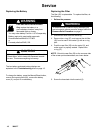
Replacing the Automatic Nozzle
The automatic noz zle ( 5b, 6b, or 7b) is not serviceable.
If it leaks, replace it as follows:
1. Relieve the pressure.
WARNING
To reduce the risk of s erious injury whenev er y ou
are instructed to relieve pr essure, always follow the
Pressure Relief Procedure on page 5.
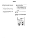
2. Remove the old nozzle from the ex tension with an
open-end adjustable wrench on the flats of the
nozzle bushing. See below.
nozzle bushing
TI0327
3. Thread the new nozzle (5b, 6b, or 7b) onto the
extension, and tighten it firmly with a n open-end
adjustable wrench.
NOTE: Only tighten the nozzle with the wr ench
on the flats of the noz zle bus hing. Do not disas-
semble the bushing from the noz zle. Disassembly
will affect the performance of the nozzle.
WARNING
Do not us e the old Graco noz zle ( Part No. 203655)
or any other manual shut-off nozzle on the PM5
extension. You must use the new automatic nozzle
that is provided with the P M5, or the meter could
be damaged. Do not use any sealant material.