


5309377
Installation
PRESSURIZED EQUIPMENT HAZARD
The equipment stays pressurized until pr essure is
manually relieved. To reduce the risk of serious
injury from pressu rized fluid, accidental spray from
the dispense valve, or splashing fluid, follow the
Pressure Relief Procedure when you
D Are instructed to r elieve pr essure
D Check, clean, or service any system equipment
D Install or clean fluid noz zles or filter
WARNING
Pressure Relief Procedure
1. T urn off the power supply to the pump.
2. T rigger the dispense valve into a waste container
to relieve pressure.
3. Open any bleed-type master air valves and fluid
drain valves in the system.
4. Leave the drain valve open until you are r eady to
pressurize the system.
FIRE AND EXPLOSION HAZARD
The movement of fluids through the
dispensing system generates static
electricity. The static electricity can
cause volatile fumes to ignite, resulting in explosion
and fire. The dispensing system must grounded.
See Grounding on page 6.
WARNING
Pre -Installation Procedure
1. Relieve the pressure.
WARNING
To reduce the risk of s erious injury whenev er y ou
are instructed to relieve pr essure, always follow the
Pressure Relief Procedure abov e.
2. Close the shut-off valve (item J i n Fig. 1 ).
3. Ground the hose and reel or c onsole. See
Grounding on page 6. Leave a minimum two
engaged threads bare when using PTFE tape. The
bare threads ensure a ground is maintained.
Installation Procedure
If this is a new installation, or if the fluid in the
lines is c ontaminated, flush the lines before you
install the metered valve. Contaminated lines
could cause the v alve to leak.
CAUTION
1. If this is an ex isting installation, go to step 7.
Steps 2 through 6 are the Flushing Procedure.
2. Close the fluid s hut-off valve (J) at each dispense
position.
3. Make sure the main fluid outlet valve at the pump
is closed, the air pr essure to the pum p motor is
adjusted, and the air v alve is open. Slowly open
the main fluid v alve.
4. Place the hose end (with no dispense valve con-
nected) into a container for waste oil. Secure the
hose in the c ontainer so it will not come out during
flushing. If you have multiple d ispense positions,
first flush the dispense position farthest from the
pump, and work y our way toward the pump.
5. Slowly open the shut-off valve (J) at the dispense
position. Flush out a sufficient amount of oil to
ensure that the entire syst em is clean, and close
the valve.
6. Repeat step 5 at all other dispense pos itions.
7. Relieve the pressure.
WARNING
To reduce the risk of s erious injury, whenever you
are instructed to relieve pr essure, always follow the
Pressure Relief Procedure at left.
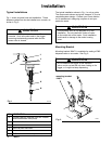
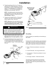
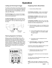
8. Slide the swivel c over (4) of the P M5 onto the
hose, small end first. See Fig. 3.
9. Apply thread sealant to the male threads of the
hose fitting, thread the hos e fitting into the swivel
(3) of the PM5, and tighten it firmly. See Fig. 3.
NOTE: Make sure you let the sealant cure to the
manufacturer’s recommendations before you let
fluid into the system.