


4 309377
Installation
Typical Installations
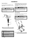
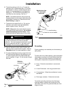
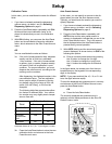
Fig. 1 shows a typical hose reel installation. These
dispense valves can also be installed on a console, as
showninFig.2.
Do not us e this d ispense valve on non-Graco
consoles. Such u se c ould result in the trigger
becoming inadvertently pressed w hile the dis-
pense valve is stowed.
CAUTION
Fig. 1
L
M
K
N
J
H
06174B
KEY DESCRIPTION
H Thermal relief kit (required) Part No. 235998
Install downs tream from pump.
J Fluid shut-off valve
K Hose
L Hose reel fluid inlet hose
M Hose reel
N PM5 electronic metered dis pense v alve
The typical installation s hown in Fig. 1 is only a guide.
The components shown are typical; however , it is not a
complete system design. Contact your Graco distribu-
tor for assistance in designing a system to suit your
parti cular needs.
This dispense valve is not designed for i n-line
installation. Do not ins tall with a shut-off v alve
on the outlet side of the meter. Such installation
could result in damage to the m eter housing
cover.
CAUTION
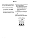
Mounting Bracket
Mounting bracket 196471 is available for resting a PM5
dispense valve on a console. See Fig. 2.
Do not obs truct the trigger of this dispense
valve, and do not set the unit down resting on its
trigger, or it might not stop dispensing.
CAUTION
mounting bracket
196471
Fig. 2
TI0334