


Pressure Control Repair
18 309977H
Pressure Control Repair
Motor Control Board
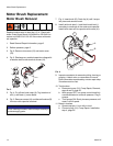
Removal
Refer to Wiring Diagram, page 29.
1. Relieve pressure; page 6.
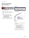
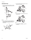
2. Remove five screws (12) and motor cover (18).
3. Cut wire tie holding wiring to motor control board
(38).
4. Disconnect at motor control board (38):
• Motor wire harness: brown (+), blue (-).
• Two line voltage leads: brown (+), blue (-).
• Lead (D) from potentiometer.
• Lead (E) from transducer.
• Two leads (F) from motor thermal switch.
5. Remove six screws (83) and circuit board (38).
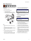
Installation
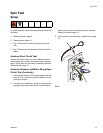
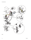
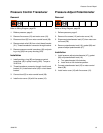
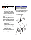
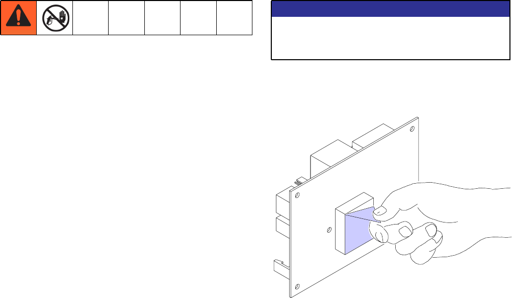
1. Fig. 7. Remove old thermal paste from control box.
Remove protective cover from thermal pad on new
motor control board.
FIG.7
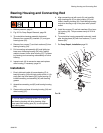
2. Fig. 6. Install motor control board (38) with six
screws (83).
3. Connect to motor control board (38):
• Two leads (F) from motor thermal switch.
• Lead (E) from transducer.
• Lead (D) from potentiometer.
• Two line voltage leads: brown (+), blue (-).
• Motor wire harness: brown (+), blue (-).
4. Bundle and tie all loose wires together.
5. Install motor cover (18) with five screws (12).
NOTICE
Electrostatic discharges can damage components
on motor control board. Use a ground strap when
handling or installing motor control board.
WLD