


Pressure Control
311019L 13
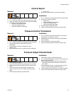
Control Board
Removal
1. Relieve pressure, page 5.
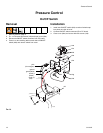
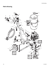
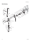
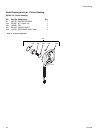
2. FIG. 14. Remove two screws (108) and open cover (62a)
3. Disconnect engine and ground wires from wire harness (66).
4. Disconnect at control board (62e):
• Lead from potentiometer (62b)
• Lead from transducer (155)
• Lead from ON/OFF switch (62d)
• Clutch wires
5. Remove four screws (62f) and control board (62e).
Installation
1. FIG. 14. Install control board (62e) with four screws (62f).
2. Connect at control board (62e):
• Clutch wires
• Lead from ON/OFF switch (62d)
• Lead from transducer (155)
• Lead from potentiometer (62b)
3. Connect engine and ground wires.
4. Close cover (62a) and secure with two screws (108).
Pressure Control Transducer
Removal
1. Relieve pressure, page 5.
2. FIG. 14. Remove two screws (108) and open cover (62a)
3. Disconnect transducer (155) lead from control
board (62e).
4. Pull transducer connector through strain relief
bushing (151).
5. Remove transducer and o-ring (99) from filter housing (67).
Installation
1. FIG. 14. Install o-ring (99) and transducer (155) in filter
housing (67). Torque to 35 - 45 ft-lb.
2. Install transducer connector and strain relief bushing in
control housing.
3. Connect lead (E) to control board (62e).
4. Close cover (62a) and secure with two screws (108).
Pressure Adjust Potentiometer
Removal
1. Relieve pressure, page 5.
2. Fig. 13.Remove two screws (108) and open cover (62a).
3. Disconnect potentiometer (62b) lead from control board
(62e).
4. Loosen set screws on potentiometer knob (62c) and
remove knob, shaft nut, lock washer and potentiometer
(62b).
5. Remove spacer (62g) from potentiometer.
Installation
1. Install spacer (62g) on potentiometer (62b).
2. F
IG. 14. Install potentiometer, shaft nut, lock washer and
potentiometer knob (62c).
a.Turn potentiometer shaft clockwise to internal stop.
Assemble potentiometer knob (62c) to strike pin on
cover (62a).
b.After adjustment of step a., tighten both set screws in
knob 1/4 to 3/8 turn after contact with shaft.
3. Connect potentiometer (62b) lead to control board (62e).
4. Close cover (62a) and secure with two screws (108).