


10 308371
Service
D If the unit requires more than installation of a
service kit, it is usually quickest and easiest to send
the unit to the Graco distributor for repair or
replacement.
D If the vanes need replacing, or if foreign material is
present in the motor chamber, an experienced
mechanic may remove the end plate opposite the
drive shaft end. Do not pry with a screwdriver. It will
dent the surface of the plate and body, causing
leaks. Use a puller tool, which will remove the end
plate while maintaining the position of the shaft.
D New vanes should have the edges with cut corners
(or the notched edges, if the vanes are reversible)
pointing toward the bottom of the vane slot.
Cleaning the Shaft
Each week, clean any dried fluid from around the
bearing (38) area of the shaft (14).
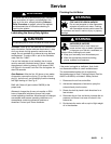
Replacing the Heavy-Duty Air Motor
(See Fig. 6)
Removing the Heavy-Duty Air Motor
1. Disconnect the air hose (21).
2. Loosen the two setscrews (32) on the collar (2)
and remove the air motor (1).
Installing the Heavy-Duty Air Motor
1. Place one-half of the coupling (3a) on the air motor
shaft (S), flush with the end of the shaft. Tighten
the coupling setscrew against the flat on the shaft.
2. Install the load cushion (P) on the gear reducer
coupling half. Slide the clamp (2) onto the collar
(4).
3. Align the two coupling halves (3a), and push the
air motor hub into the collar (4) until it bottoms out,
then back it out 0.015 in. (0.38 mm). Make sure
the air motor inlet and outlet face up.
4. Apply Loctiter No. 222 to the two clamp setscrews
(32). Align the setscrews to one side of the slots
on the collar (4), and tighten them.
5. Apply pipe thread sealant to the inlet (20) and
outlet (22) fittings, and install them in the air motor.
Fig. 6
P
4
32
2
S
22
20
1
3a
Apply Loctite No. 222.
1
Apply low-strength thread sealant.
2
2
1
2
L
T
21
2266B
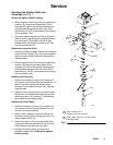
Replacing the Heavy-Duty Gear Reducer
(See Fig. 7)
1. Do not attempt to repair the gear reducer (5)
yourself. Contact your Graco distributor.
2. When replacing the gear reducer, turn it upside
down and remove the cap screws (33) and
washers (40) from the bottom of the old gear
reducer. Remove the top coupling half (19a) from
the old gear reducer, and install the coupling half
on the new gear reducer. Wipe the screw holes
clean with a rag.
3. Apply Loctite No. 271, or equivalent, to the four
cap screws (33). Install them with the washers (40)
through the bracket (6) and into the gear reducer.
Make sure the three hole pattern on the bottom of
the bracket (6) is orientated in relation to the gear
reducer (5) as shown in Fig. 7. Run the agitator
to let the bracket (6) center itself. Torque the
screws to 160 in-lb (18 NSm). Leave the gear
reducer upside down for 30 minutes to allow the
Loctite to cure. Set the coupling as instructed
under Setting the Agitator Shaft Coupling, on
page 11.
Do not use the four screws supplied with the new
gear reducer to secure it; those screws will not
properly secure the gear reducer. Use the cap
screws and washers (33 and 40) removed from the
old gear reducer. Be careful not to spill any oil from
the gear reducer.
CAUTION