


6 308371
Installation
If installing an agitator onto a non-agitated tank,
follow steps 1, 2, and 7 through15. If installing a
heavy-duty agitator in place of a standard agitator,
follow pages 1, 3 through 12, 14, and 15.
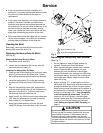
1. Follow the Pressure Relief Procedure above.
Then remove the pressure tank cover from the
tank.
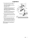
2. See Fig. 3. Unscrew and remove the hex jam nut
(C), plug (D), and O-ring (E) from the tank cover.
3. Remove the upper U-bolt (26).
4. See Fig. 4. Loosen the two set screws (13) and
remove the agitator paddle (12).
5. On 10 and 15 gallon tanks, remove the lower
U-bolt (26), loosen screws (24) and slide the baffle
(23) off the fluid tube (K).
6. Unscrew and remove the hex jam nut (C), gasket
(17), and agitator from the tank cover.
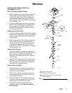
7. See Fig. 3. Place the gasket (17) on top of the
tank cover center hole. Insert the agitator drive
shaft (14) through the center hole.
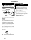
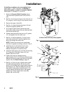
NOTE: Position the air motor so it faces away
from the air regulator mounting as shown in Fig. 2.
8. Install the jam nut (C) below the tank cover.
Tighten the jam nut firmly to assure a seal
between the gasket (17) and tank cover.
9. Install the shaft support (11) onto the shaft housing
(9). Clamp with U-bolt (26), clamp (10), lock
washer (36) and nut (25).
10. Tighten the U-bolt at a position leaving
approximately 0.015 in. (0.006 mm) clearance gap
between the thrust washer and the top of the shaft
support. See the Parts Drawing on page 12.
11. See Fig. 4. On the 10 and 15 gallon tanks, place
the lower bearing assembly (2) and (3) on the
shaft. On the 5 gallon tank, clamp U-bolt directly to
shaft support (11). Slide the baffle (23) over the
fluid tube (K) and position the baffle about 1/2 in.
(13 mm) above the highest point on the agitator
paddle (12). Clamp in place with U-bolt (26),
washer (36), and nut (25).
Fig. 2
B
A
5 Gallon Tank with Heavy-Duty Agitator
03282A
03261B
Fig. 3
9
17
14
C
11
D
14 (REF)
26
E
F
36
10
25