


308371 11
Service
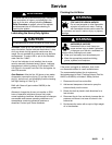
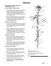
Servicing the Agitator Shaft and
Couplings (See Fig. 7)
Setting the Agitator Shaft Coupling
1. With the agitator shaft (14) pushed up against the
washer (15a), secure the lower portion of the
coupling half (19b) to the shaft by tightening the
coupling setscrew against the flat on the shaft.
Leave about a 0.015 in. gap between the coupling
half and washer (15b).
2. Secure the upper coupling half (19a) to the gear
reducer shaft by tightening the coupling setscrew
into the keyway. Leave about a 0.015 in. gap
between each of the coupling halves (19a, 19b)
and the load cushion (R).
Replacing the Agitator Shaft
1. Remove the agitator paddle. Remove the setscrew
from the lower coupling (19b). Pull out the agitator
shaft (14) and install the new shaft. Replace the
agitator paddle.
2. With the agitator shaft (14) pushed up against the
washer (15a), secure the lower portion of the
coupling half (19b) to the shaft by tightening the
coupling setscrew against the flat on the shaft.
Leave about a 0.015 in. gap between the coupling
half and washer (15b).
Replacing the Coupling
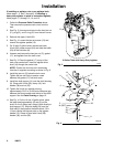
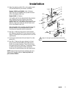
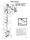
1. Remove the three cap screws (18), washers (7)
and spacers (8) from the mounting bracket (6). Lift
the air motor and gearbox off the tank cover.
Remove the two coupling halves (19a, 19b) from
the shaft ends.
2. Install the new coupling halves on the shaft ends.
Replace the air motor/bracket assembly and the
three cap screws (18), washers (7) and spacers
(8) to fasten the mounting bracket.
Replacing the Shaft Seals
1. Remove the three cap screws (18), washers (7),
and spacers (8) from mounting bracket (6), and
move the air motor assembly.
2. With air motor assembly removed, remove the
setscrew from the lower coupling half (19b). Pull
out the agitator shaft (14).
3. Remove the hex nut (16) and remove the shaft
housing (9). Remove the seals (9a, 9b) from the
shaft housing, and install the new seals.
4. Reinstall the shaft housing and shaft. Use
installation steps listed in Setting the Agitator
Shaft Coupling.
Apply Loctite No. 271.
Torque to 160 in-lbs (18 N-m)
Install seals with open spring-loaded
side toward tank
2
1
5
19a
19b
15b
R
9a
2
9
9b
15a
14
Fig. 7
6
40
18
1
8
7
14 (REF)
16
2
33
2267C