


Installation
332245E 7
General Information
NOTE: Reference numbers and letters in parentheses
in the text refer to the callouts in the figures.
NOTE: Always use Genuine Graco Parts and Accesso-
ries, available from your Graco distributor. If you supply
your own accessories, be sure they are adequately
sized and pressure-rated for your system.
F
IG
. 1 is only a guide for selecting and installing system
components and accessories.
Prepare the Operator
All persons who operate the equipment must be trained
in the operation of all system components as well as the
proper handling of all fluids. All operators must thor-
oughly read all instruction manuals, tags, and labels
before operating the equipment.
Prepare the Site
Ensure that you have an adequate compressed air
supply.
Bring a compressed air supply line from the air com-
pressor to the pump location. Be sure all air hoses are
properly sized and pressure-rated for your system. Use
only electrically conductive hoses. The air hose should
have a 3/8 npt(m) thread. For best performance, use 1/2
in. air line or larger.
Keep the site clear of any obstacles or debris that could
interfere with the operator's movement.
Have a grounded, metal pail available for use when
flushing the system.
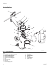
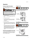
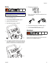
Components
See F
IG
. 1.
• The red-handled bleed-type master air valve (C) is
required in your system to relieve air trapped
between it and the air motor when the valve is
closed. Do not block access to the valve.
• The pump air regulator (E) controls pump speed
and outlet pressure by adjusting the air pressure to
the pump.
• The air relief valve (not shown) opens automatically
to prevent overpressurization of the pump.
• The airless spray gun (H) dispenses the fluid. The
gun houses the spray tip (not shown), which is avail-
able in a wide range of sizes for different spray pat-
terns and rates of flow. Refer to gun manual for tip
installation.
• The hose (J) provides the gun fluid supply.
• The suction hose (R) with strainer allows the pump
to draw fluid from a 5 gallon (19 liter) pail.
• A optional fluid filter with a 60 mesh (250 micron)
stainless steel element filters particles from fluid as
it leaves the pump.
• A fluid drain valve (G) relieves fluid pressure in the
hose and gun.
Air Lines Accessories
Install the following accessories in the order shown in
F
IG
. 1, using adapters as necessary.
• An air-line filter (B) removes harmful dirt and mois-
ture from the compressed air supply.
• A second bleed-type air shutoff valve (A) isolates
the air line accessories for servicing. Locate
upstream from all other air line accessories.
Trapped air can cause the pump to cycle
unexpectedly, which could result in serious injury
from splashing or moving parts.