


309414 13
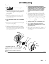
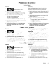
Pressure Control
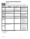
Control Board
Removal
1.
Relieve press ure; page 4.
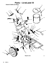
2. Fig. 6. Remove four screws (93) and
display/cover (139). Pull display connector wings
open on PC board and pull display connector out.
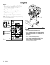
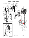
3. Fig. 14. Disconnect at control board (109):
D Lead (D) from potentiometer.
D Lead (E) from trans ducer.
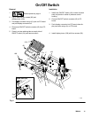
D Remove ON/OFF switch (24) connecto r (A).
4. Fig. 6. Remo ve six screws (214) from control board
(109) and green ground wire.
5. Remove two connectors (Y) at backside of pres-
sure control. Remove jam nuts (Z) and contro l
board (109).
Installation
When installing replacement control board, fo llow
instru ctions with control board to set model type.
1. Fig. 6. In stall control board (109) and jam nuts (Z).
Install two connectors (Y) at backside of pressure
contro l.
2. Install green ground wire and contr ol board (109)
with six screws (214).
3. Fig. 14. Connect to contr ol board (109):
D Connect ON/OFF switch (24) connector (A).
D Lead (E) to transducer.
D Lead (D) to potentiometer .
4. Fig. 6. Push display connector into PC board clos e
display connec tor wings on PC board. Install
display/cover (139) with four screws (93).
Pressure Control Transducer
Removal
1.
Relieve press ure; page 4.
2. Fig. 6. Remove four screws (93) and
display/cover (139).
3. Disconnect lead (E) from contr ol board (109).
4. Remove tw o screws (201) that connect control
housing (108) to filter housing (200e). Fro m inside
of control box, pull transducer connecto r through
contr ol housing (108).
5. Remove pres sure control transducer (200p) and
o-ring (200r ) from filter housing (200e).
Installation
1. Fig. 6. Install o-ring (200r ) and pressure control
trans ducer (200p) in filter housing (200e). Torque
to 30 --36 ft-lb.
2. Install transducer cable thr ough control box. Ins tall
filter housing and spacer to control box with two
screws (201).
3. Connect lead (E) to motor control board (109).
4. Install display/cover (139) with four sc rews (93).
Pressure Adjust Potentiometer
Removal
1.
Relieve press ure; page 4.
2. Fig. 6. Remove four screws (93) and
display/cover (139).
3. Disconnect lead (D) from contr ol board (109).
4. Loosen set screws on potentiomete r knob (19) and
remove knob, shaft nut, lockwasher and pressure
adjust potentiometer (81).
5. Remove seal (148) from potentiometer (81).
Installation
1. Install seal (148) on potentiometer (81).
2. Fig. 6. In stall pressu re adjust potentiometer (81),
shaft nut, lockwasher and potentiomete r knob (19).
a. T urn potentiomete r shaft (81) clock wise to
internal stop. Assemble potentiometer knob
(19) to strike pin on plate (23) .
b. After adjustment of step a., tighten both set
screws in knob 1/4 to 3/8 turn after contact
with shaft.
3. Connect lead (D) to control board (109).
4. Install display/cover (139) with four sc rews (93).