


309414 15
Displacement Pump
Removal
1. Flush pump.
2.
Relieve press ure; page 4.
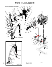
3. Fig. 8. Cyc le pump with pisto n rod (222) in its
lowest position.
4. Fig. 8. Remo ve suction tube (12) and hose (61).
Fig. 8
7672C
222
61
12
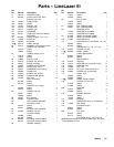
5. Fig. 9. Use sc rewdriver: push retaining spri ng up
and push out pin (96).
Fig. 9
7675B
96
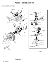
6. Fig. 10. Loosen lock nut by hitti ng firmly with a
20 oz (maximum) hammer. Unscr ew pump.
Fig. 10
7673B
Repair
See manual 309277 fo r pump repair instructions.
Installation
WARNING
If pin works loose, parts could break off due to
forc e of pumping action. Parts could project
through the air and result in serious injury or prop-
erty damage. Make sure pin and reta ining spring
are properly installed.
C
A
UTION
If the pump lock nut loosens during operation, the
threads of the bearing housing will be damaged.
Make sure locknut is properly ti ghtened.
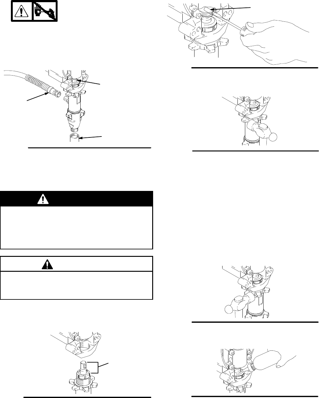
1. Fig. 11. Pull pisto n rod out 1.5 in. Scr ew in pump
until holes in bearing cross link and piston rod
align.
Fig. 11
7676B
1.5 in.
2. Fig. 9. Push pin (96) into hole. And push retaining
spring into groove a ll the way around connec ting
rod.
Fig. 12. Screw jam nut down onto pump until nut
stops. Screw pump up into bearing housing until it is
stopped by jam nut. Back off pump and jam nut to
align pump outlet to back. T ighten jam nut by hand,
thentap1/8to1/4turnwitha20oz(maximum)ham-
mer to approx imately 75 5ft--lb(102N¡m).
Fig. 12
7673B
Fig. 13. Fill packing nut with Gr aco TSL until fl uid flows
onto the to p of seal.
Fig. 13
7677B