


309414 7
Troubleshooting
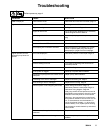
PROBLEM CAUSE SOLUTION
Gallon counter not working Broken or disconnected wire Check wires and connections. Replace
broken wires.
Bad sensor Replace sensor
Missing magnet Replace magnet. Locate in correct spot.
Sprayer operates, but display does not Bad connection between control board
and display
Remove display and reconnect
Display damaged Replace display
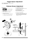
Distance c ounter not operating properly Trigger sensor not set correctly See “Spray icon does not show on dis-
play when fluid is sprayed”
Bad wiring connections Check connector, and reconnect
Distance sensor not spaced correctly
from gear
Adjust space between sensor and gear
to .050 -- /+ .020”
Distance and gear not aligned Remove tire, and press in or pull out
gear to align sensor and gear.
Gear teeth missing or damaged. Replace distance gear/wheel
Wire cracked or broken Replace sensor
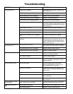
Mils not calculating Distance s ensor See “Distance counter not operating
properly”
Trigger sensor See “Spray icon does not show on dis-
play when fluid is sprayed”
Gallon counter See “Gallon counter not working”
Bad or damaged control board Replace control board
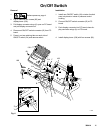
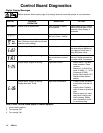
Fluid spray starts after spray icon is
shown on display
Interrupter (213) is improperly positioned Turn screw (215) counterclockwise until
spray icon synchronizes with fluid spray
Fluid spray starts before spray icon is
shown on display
Interrupter (213) is improperly positioned Turn screw (215) clockwise until spray
icon is synchronized with fluid spray
Spray icon does not show on display
when fluid is sprayed
Loose connector Check that 5-pin connector and reed
switch are properly connected
Interrupter (213) is improperly positioned Turn screw (215) counterclockwise until
spray icon synchronizes with fluid spray
Reed switch assembly (207) is damaged Replace reed switch assembly (207)
Magnet on assembly (207) is missing Replace reed switch assembly (207)
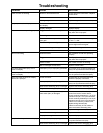
A connector on wiring harness (58) or on
reed switch (207) is damaged
Disconnect reed switch and 5-pin con-
nector from back of control board.
Check continuity between pin 1 on 2-pin
connector and pin 1 on 5-pin connector.
Check continuity between pin 2 on 2-pin
connector and pin 4 on 5-pin connector.
If there is no continuity in either case,
replace wiring harness (58).
If there is continuity in both cases re-
place reed switch assembly (207).
Cut or sliced wire Replace wiring harness (58)
Control board is damaged Replace control board
Display is damaged Replace display
Spray icon is always shown on display Interrupter (213) is improperly positioned
Turn screw (215) clockwise until spray ico n
is synchronized with fluid spray
Reed switch assembly (207) is damaged Replace reed switch assembly (207)