


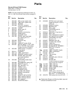
18 820-133
Service
Repairs,
other than those
for which instructions are given
below,
should be performed by a trained and qualified re
-
pair
agency
.
WARNING
To reduce the risk of injury, including fluid injection,
splashing in the eyes or on the skin, or injury from
moving parts, always follow the Pressure Relief
Procedure
W
arning
on
page 1
1 before checking or
repairing any part of the spray system.
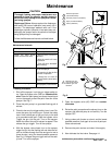
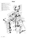
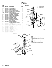
Inlet Check V
alve
. See Fig. 15.
1. Unscrew the inlet check valve (26) from the paint
pump (22).
2. Clean
the gasket (26a), the inlet valve (26), and the
paint
pump (22) threads and check for
erosion. If any
of
the parts are eroded, replace them.
3.
Be sure the threads in the paint pump are clean.
4. Lubricate the threads of the inlet valve with petro-
leum
jelly
. Install the gasket on the valve, then
install
the
valve and
torque it to 320–360 in–lb (36–41 N.m).
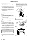
Outlet
Check V
alve.
See Fig. 15.
1.
Unscrew the plug (28d) and the housing (28b).
2. Use a pick, such as a dentist’s pick, to remove the
seal
(28a) from the paint pump (23). The seal may be
hard
to remove.
DO NOT
LEA
VE THE SEAL IN THE
PAINT
PUMP HOUSING.
3. Clean the parts thoroughly, including the threads in
the
pump, with a compatible solvent.
Check all parts
for
wear or damage and replace as needed.
4.
Lubricate the threads of the housing (28b) and plug
(28d).
5. Install a NEW seal (28a) in the pump housing. AL-
WAYS
replace
the seal (28a). Do not try to reuse the
old
seal as it will be deformed.
CAUTION
Be
sure you do not install a new seal until the old one
is
removed. Having two seals in the
valve will cause
performance
problems.
6. Install
the housing (28b) and torque to 125–150 in–lb
(14–17
N.m).
7. The last coil on one end of the spring is turned in.
Place
this end over the stud in the plug (28d). Install
the ball (28e), washer (28f) and plug, and torque to
plug
to 380–300 in–lb (32–34 N.m).
Pressure Control.
See Fig. 15.
When
removing the pressure control (4) to check or clean
it,
always replace the seal (4a). When replacing the pres
-
sure
control, torque the new control (4) to 125–150
in–lb
(14–17
N.m).
Starter Switch.
See Fig. 15.
Remove the cover of the switch box. Remove the two
screws
holding the starter switch (18a). Remove the old
switch
and install a new one.
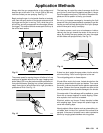
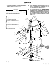
Diaphragm.
See Fig. 15.
1. Remove
the
inlet strainer (27). Remove the four paint
pump
screws (25) and lockwashers (24).
2. Remove the bypass valve (66) and the fluid outlet
nipple (67), and then remove the screws (35) and
shield (3).
3. Remove
the
screw (36) and lockwasher (37) from the
bracket (38).
4. Pull
the paint pump assembly away
from the hydrau
-
lic
housing (20) and remove the old diaphragm
(21).
CAUTION
Never
start the electric motor with the inlet valve
(26)
removed
to avoid damaging the diaphragm.
CAUTION
Be
careful not to get any dirt or
paint on the new dia
-
phragm or the hydraulic housing. Contaminants in
the hydraulic system can cause the sprayer to mal-
function
and result in costly damage to the sprayer
.
DO
NOT T
AMPER with the nut (C). The nut is factory
set
to hold the spring to a specific dimension.
5. Check
the gasket (22a) for wear or damage and
re
-
place it if needed. Clean the top of the paint pump
and
the hydraulic housing thoroughly
.
6. Install the new diaphragm assembly (21), lubricate
the internal threads of the housing (20), and reas-
semble
the parts.