


Installation
10 313516G
Installation
The Automatic AirPro spray gun can spray
most coatings or finishes currently being used
for automotive, industrial, aerospace, marine,
wood, plastic and architectural applications,
while easily operating from paint delivery sys-
tems, such as pressure pots or remote pumps
for production line operation.
The air regulator must have a minimum air flow
capacity of 30 scfm at 100 psi (0.7 MPa, 7.0
bar) air pressure.
Ventilate Spray Booth
• Check and follow all national, state, and
local codes regarding air exhaust velocity
requirements.
• Check and follow all local safety and fire
codes.
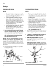
Configure Gun and Manifold
The gun is supplied with an internal fluid plug
and seals (19, 20, 21). To use the gun in a cir-
culating system, remove the internal plug. In a
non-circulating system, leave the plug in place
to minimize flush time.
Circulating System
1. Apply anti-seize lubricant to the threads
and mating faces of the manifold (101) and
the elbows (107), supplied unassembled.
2. Install the elbows (107) in both fluid ports of
the manifold (101).
3. Connect the fluid supply line to one elbow
and the fluid return line to the other. The
manifold fluid ports are reversible.
4. Install the gun on the manifold, using the
four screws (13). Start the threads of all
four screws. Tighten the front two screws
first, and then tighten the back two. Torque
all four screws evenly to 65 in-lb (7.3 N•m).
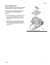
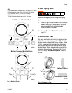
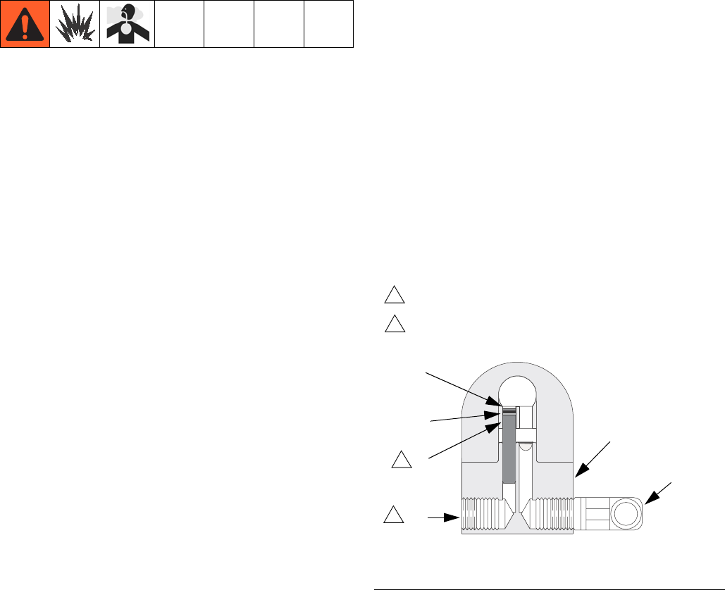
Non-circulating System
1. See FIG. 1. Apply anti-seize lubricant to the
threads and mating faces of the manifold
(101), plug (109), and elbow (107), sup-
plied unassembled.
2. Install an elbow (107) in one fluid port of
the manifold (101), and a plug (109) in the
other port.
3. Install the internal plug (19) in the gun fluid
port on the same side as the manifold plug.
4. Connect the fluid supply line to the fluid
inlet elbow (107).
5. Install the gun on the manifold, using the
four screws supplied. Start the threads of
all four screws. Tighten the front two
screws first, and then tighten the back two.
Torque all four screws evenly to 65 in-lb
(7.3 N•m).
FIG. 1: Non-Circulating Setup Shown (cutaway view)
Remove when used in circulating systems.
1
ti8587b
1
Replace with elbow (107) when used in
circulating systems.
2
2
19
101
107
109
21
20