


Setup
14 313516G
Setup
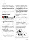
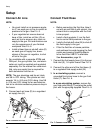
Connect Air Line
NOTE:
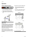
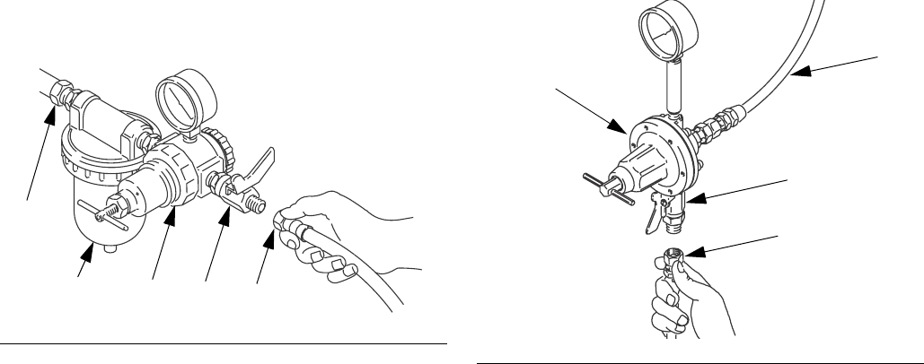
• You must install an air pressure regula-
tor (F) on each gun air line to control air
pressure to the gun. See FIG. 6.
• If your regulated air source does not
have a filter, install an air filter (G) on
each air line to ensure a dry, clean air
supply to the gun. Dirt and moisture can
ruin the appearance of your finished
workpiece. See FIG. 6.
• Install a bleed type air shutoff valve (E)
on each gun air supply line, down-
stream of the gun air regulator, to shut
off air to the gun.
1. For manifolds with a separate ATOM and
FAN port, the gun cylinder, fan, and atomi-
zation air must be supplied and regulated
separately. For the manual fan valve mani-
fold, only one supply line is required for
both atomization and fan air.
NOTE: The gun atomizing and fan air inlets
are 3/8 in. O.D. tubing. The cylinder air inlet
accepts 1/4 in. (6.3 mm) O.D. tubing. Use 3/8
in. (9.5 mm) O.D. tubing for fan and atomiza-
tion air to minimize excessive pressure drop in
the hoses.
2. Connect each air hose (D) to a regulated
air supply line (H).
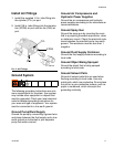
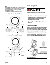
Connect Fluid Hose
NOTE:
• Before connecting the fluid line, blow it
out with air and flush it with solvent. Use
solvent that is compatible with the fluid
to be sprayed.
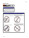
• Install a fluid regulator (L) on the fluid
line to control fluid pressure to the gun.
• Install a fluid shutoff valve (M) to shut off
the fluid supply to the gun.
• Filter the fluid line of coarse particles
and sediment to avoid clogging the fluid
nozzle and causing finishing defects.
Inline fluid filter 24B707 is available.
See Accessories, page 34.
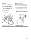
1. Connect the fluid supply hose (J) to the gun
fluid inlet (S), 1/4 npsm thread. See FIG. 8.
2. Connect the other end of the fluid hose (J)
to a regulated fluid supply outlet (M).
3. In a circulating system, connect a
grounded fluid return hose to the gun fluid
outlet (T). See FIG. 8.
In a non-circulating system, remove the
gun fluid outlet fitting (T) and plug the outlet
port with the pipe plug supplied. See FIG. 8.
FIG. 6: Connect Air Line
ti01990
H
G
FED
FIG. 7: Connect Fluid Hose.
M
L
K
J
ti7016a