


6 306706
Installation
NOTES:
D Reference numbers and letters in parentheses in
the text refer to the callouts in the figures and the
parts drawing.
D Accessories are available from your Graco repre-
sentative. If you supply your own accessories, be
sure they are adequately sized and pressure-rated
to meet the system’s requirements.
Grounding
Proper grounding is an essential part of maintaining a
safe system.
To reduce the risk of static sparking, the pump, mount-
ing cover, and all electrically conductive objects or
devices in the spray area must be properly grounded.
Check your local electrical code for detailed grounding
instructions for your area and type of equipment.
For a ground wire and clamp, order
Part No. 237569.
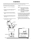
Pump: Connect one end of a 12 ga (1.5 mm@) mini-
mum ground wire (A) to the ground connector (B) on
the pump. See Fig. 1. Connect the other end of the
wire to a true earth ground.
Agitator and drum cover: Connect one end of ground
wire (A) to ground connector (B) on rim of drum cover.
See Fig. 1. Connect other end of ground wire to true
earth ground.
A
Fig. 1
B
Air and fluid hoses: Use only electrically conductive
hoses with 500 ft (150 m) maximum combined hose
length to ensure grounding continuity.
Air compressor: Follow manufacturer’s recommenda-
tions.
Spray gun: Connect to a properly grounded fluid hose
and pump.
Object being sprayed: Follow your local code.
Fluid supply container: Follow your local code.
Solvent pails used when flushing: Follow your local
code. Use only metal pails, which are conductive,
placed on a grounded surface. Do not place the pail
on a nonconductive surface, such as paper or card-
board, which interrupts the grounding continuity.
To maintain proper grounding continuity when flushing
or relieving pressure, always hold the metal part of the
spray gun firmly to the side of a grounded metal pail,
then trigger the gun.
Positioning the Unit
D Select a convenient location for the unit. The air
valves for the pump (37), agitator (5), and elevator
(3) must be fully accessible.
D The elevator needs 9 ft (2.8 m) of overhead clear-
ance. Bolt the elevator to the floor as shown in the
elevator instruction manual 306287.
System Accessories
A bleed-type master air valve (A) and a fluid drain
valve (M) are required in your system. These
accessories help reduce the risk of serious injury,
including fluid injection and splashing of fluid in the
eyes or on the skin, and injury from moving parts if
you are adjusting or repairing the pump or agitator.
The bleed-type master air valve relieves air
trapped between this valve and the pump after the
air is shut off. Trapped air can cause the pump to
cycle unexpectedly. Locate the valve close to the
pump. Order Part No. 107141.
The fluid drain valve assists in relieving fluid pres-
sure in the displacement pump, hose, and gun.
Triggering the gun to relieve pressure may not be
sufficient. Order Part No. 210658.
WARNING