


306706 7
Installation
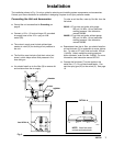
The installation shown in Fig. 2 is only a guide for selecting and installing system components and accessories.
Contact your Graco distributor for assistance in designing a system to suit your particular needs.
Connecting the Unit and Accessories
D Ground the unit as described in Grounding on
page 6.
D Connect a 1/2 in. (13 mm) minimum ID, grounded
air supply hose to the 1/2 in. npt(f) air inlet
swivel (32).
D The main air supply must include a bleed-type
master air valve (A) for shutting off air pressure to
the unit.
D The fluid line must include a fluid drain valve (not
shown), which helps relieve fluid pressure in the
hose and gun.
D You should install an air line filter (B) to remove dirt
and moisture from the air supply.
To order an air line filter, order by Part No. from the
list below:
203421 1/2” npt inlet and outlet, with gauge,
200 psi (1.4 MPa, 14 bar) maximum
working pressure. See instruction
manual 306393.
204856 1/2” npt inlet and outlet, without gauge,
200 psi (1.4 MPa, 14 bar) maximum
working pressure. See instruction
manual 306393.
D Downstream from the air filter, you should install an
air line lubricator (C) for automatic air motor lubrica-
tion. To order a 1/2” npt(f) inlet and outlet, 250 psi
(1.4 MPa, 14 bar) maximum working pressure
airline lubricator, order Part No. 214848. For more
information, see instruction manual 307316.
D Connect the fluid hose (7) to the nipple on the
outlet filter (17). Do not use thread sealer. Con-
nect the spray gun (20) to the swivel (5). See page
10.
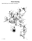
Fig. 2
04280
See DETAIL A
NOTE: Valve feet must
contact perforated plate.
DETAIL A
A
32
B
C
pump
agitator
elevator
05511