


10 308864
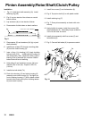
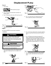
Pinion Assembly/Rotor/Shaft/Clutch/Pulley
Installation
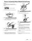
1. Fig. 10. Install jack shaft assembly (3c). Install
retaining ring (3b).
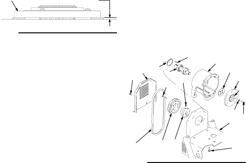
2. Fig. 9. Lay two stacks of two dimes on smooth
bench surface.
3. Lay armature (4a) on two stacks of dimes.
4. Press center of clutch down on bench surface.
Fig. 9
4a
8705A
0.12 ±.01 i n. (3.0 ±.25 mm)
5. Place spacer (3f) and armature (3d, 3g) on jack
shaft assembly.
6. Install three screws (27) through mounting plate
(D) and into clutch housing (3).
7. Insta
to
ll key (1) in bushing (112). Apply Locktite
E
to three bolts (112). Install bushing in pulley (2)
with three bolts (112b). Install set screw (112a) in
bushing. End of jackshaft (3c) must be 0.090 in.
below flush with end of bushing.
8. Hold pulley (2) and install four screws (3a) and
washers (3h) in hub (3d). Torque to 125 in-lb
(14 N¡m).
9. Install drive belt shield (74).
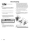
10. Push drive housing (12) and pinion housing (8)
assembly onto clutch housing (3). Tap lightly on
front of bearing housing (17) with a plastic mallet
to push drive housing and pinion housing assem-
bly onto clutch housing.
11. Install five screws (5) and lockwashers (6).
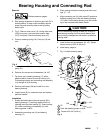
12. Fig. 8. Ta p pinion shaft (A) in with plastic mallet.
13. Install retaining ring (Z).
14. Fig. 7. Place pinion a ssembly on bench with rotor
side up.
15. Apply locktite to screws. Install four screws (39)
and lockwashers (6). Alternately torque screws to
125 in-lb until rotor is secure.
16. Install pinion assembly with five screws (5) and
lockwashers (6).
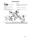
17. Fig. 5. Connect field cable (X) to pressure control.
Fig. 10
3h
3a
3g
8741A
3e
3b
1
3c
74
71
112a
68
112
27
D
3f
112b
2
3d