


12 308864
Pressure Control
Control Board
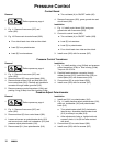
Removal
1.
Relieve pressure; page 4.
2. Fig. 11. Remove five screws (307) and
cover (322).
3. Fig. 18. Disconnect at control board (302):
D Four clutch leads: two violet and two black.
D Lead (D) from potentiometer .
D Lead (E) from transducer.
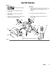
D T wo red leads (A) to ON/OFF switch (80).
4. Remove five screws (303), green ground wire and
circuit board (302).
Installation
1. Fig. 11. Install control board (302) and green
ground wire with five screws (303).
2. Connect to control board (302):
D T wo red leads (A) to ON/OFF switch (309).
D Lead (E) to transducer .
D Lead (D) to potentiometer.
D Four clutch leads: two violet and two black.
3. Install cover (322) with five screws (307).
Pressure Control Transducer
Removal
1.
Relieve pressure; page 4.
2. Fig. 11. Remove five screws (307) and
cover (322).
3. Disconnect lead (E) from control board (302).
4. Remove three screws (319) and fluid filter (318)
from control plate (301). Carefully pull transducer
connector through rubber grommet (315).
5. Remove pressure control transducer (318z) and
packing o-ring (318aa) from filter housing (318a).
Installation
1. Fig. 11. Install packing o-ring (318aa) and pressure
control transducer (318z) in filter housing (318a).
Torque to 30--35 ft-lb.
2. Carefully feed transducer connector through
rubber grommet (315). Install fluid filter (318) on
control plate (301) with three screws (319).
3. Connect lead (E) to control board (302).
4. Install cover (322) with five screws (307).
Pressure Adjust Potentiometer
Removal
1.
Relieve pressure; page 4.
2. Fig. 11. Remove five screws (307) and
cover (322).
3. Disconnect lead (D) from control board (302).
4. Loosen set screws on potentiometer knob (313)
and remove knob, shaft nut, lockwasher (310) and
pressure adjust potentiometer (310).
5. Remove seal (311) from potentiometer (310).
Installation
1. Install seal (311) on potentiometer (310).
2. Fig. 11. Install pressure adjust potentiometer (310),
shaft nut, lockwasher (310) and potentiometer
knob (313).
a. T urn potentiometer shaft (310) clockwise to
internal stop. Assemble potentiometer knob
(313) to strike pin on plate (312).
b. After adjustment of step a., tighten both set
screws in knob 1/4 to 3/8 turn after contact
with shaft.
3. Connect lead (D) to control board (302).
4. Install cover (322) with five screws (307).