


9308864
Pinion Assembly/Rotor/Shaft/Clutch/Pulley
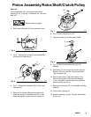
Removal
If pinion assembly (8) is not removed from clutch
housing (3), do 1. through 4. Otherwise, do 1 and then
startat5.
1.
Relieve pressure; page 4.
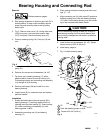
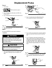
2. Disconnect field cable (X) from pressure control.
Fig. 5
X
8739A
Bottom View
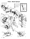
3. Fig. 6. Remove five screws (5) and lockwashers
(6) and pinion assembly (8).
5
6
5
6
Fig. 6
8740A
8
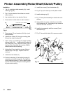
4. Fig. 7. Place pinion assembly (8) on bench with
rotor side up.
5. Remove four screws (39) and lockwashers (6).
Install two screws in threaded holes (E) in rotor.
Alternately tighten screws until rotor comes off.
Fig. 7
E
39
6
8701A
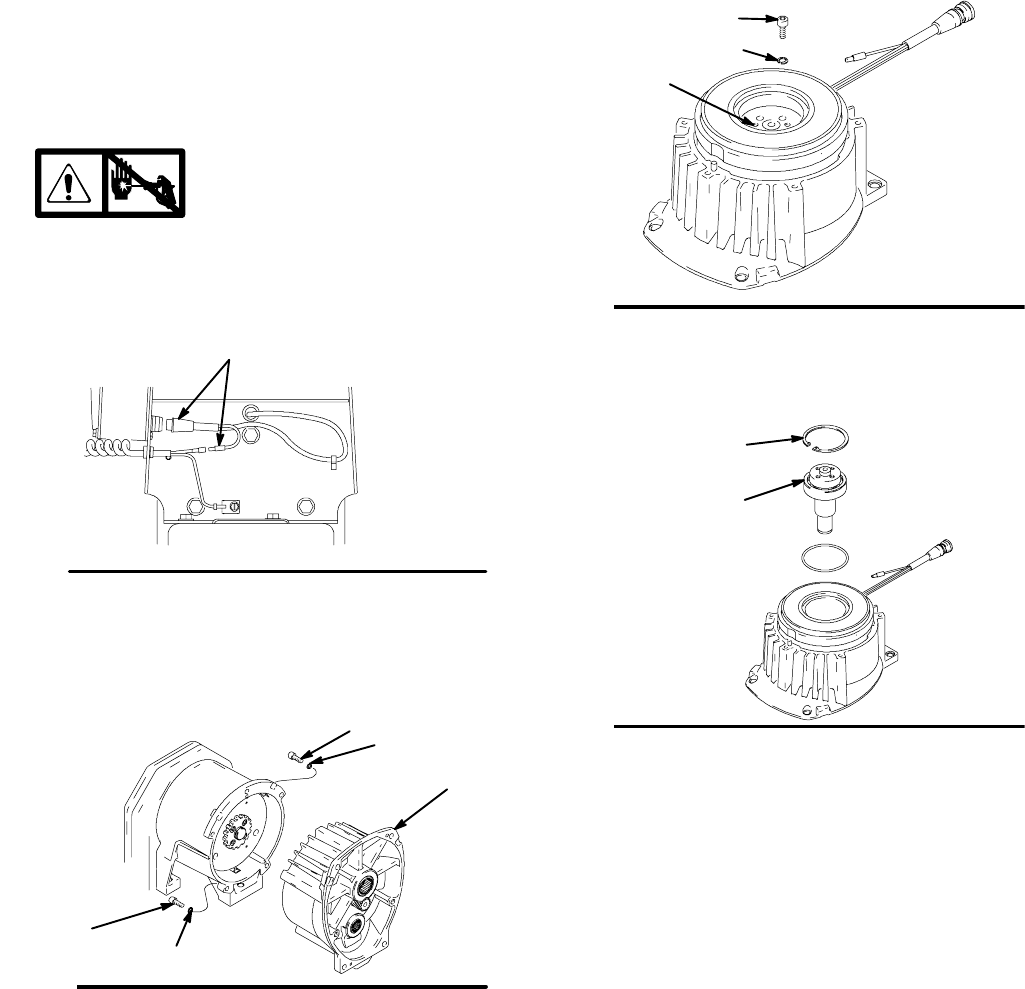
6. Fig. 8. Remove retaining ring (Z).
7. Tap pinion shaft (A) out with plastic mallet.
Fig. 8
Z
A
8703A
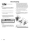
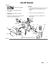
8. Fig. 10. Remove drive belt shield (74) and
belt (68).
9. Hold pulley (2) and remove four screws (3a) and
washers (3h) from hub (3d). Remove armature
(3g) and spacer (3f).
10. Remove set screw (112a) from bushing (112).
Remove three bolts (112b) and three washers
(112c). Use bolts to remove pulley from bushing.
Remove pulley and key (1).
11. Remove three screws (27) from beneath mounting
plate (D).
12. Lift off clutch housing (3).
13. Remove retaining ring (3b). Pull jack shaft assem-
bly (3c) out.