


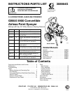
3308864
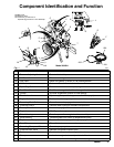
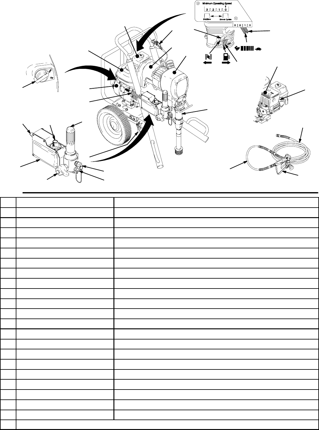
Component Identification and Function
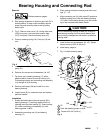
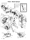
Fig. 1
203
204
202
U
W
A
B
F
K
202Main hose
203Whip end hose
204Contractor gun with RAC 5
DripLess tip guard and 517 size SwitchTip
M
L
N
Model 232624
C
D
E
G
H
J
P
R
S
T
V
8738A
X
Y
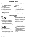
A Pressure Control Switch ON/OFF, enables/disables clutch function
B Pressure Adjusting Knob Controls fluid outlet pressure
C Air Cleaner* Filters air entering carburetor
D Fuel Tank* Holds 0.95 gallons (3.6 liter) of 86 octane gasoline
E Muffler* Reduces noise of internal combustion
F Spark Plug Cable* Routes electrical current to spark plug
G Fuel Shutoff Lever* On/off lever to regulate fuel flow from gasoline tank to carburetor
H Choke* Enriches air/gasoline mixture for cold starting
J Throttle Lever* Adjusts engine speed for large or small orifice spray tips
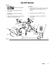
K Engine Switch* Enables/disables engine operation
L Secondary Fluid Outlet Second hose and spray gun is connected here
M Pressure Control Controls clutch cycling to maintain fluid pressure
N Primary Fluid Outlet Hose and spray gun is connected here
P Engine* 5.5 HP gasoline engine
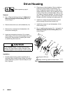
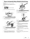
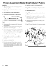
R Clutch Housing T ransfers power from engine to drive assembly
S Drive Housing T ransfers power from clutch to displacement pump
T Displacement Pump Provides fluid to be sprayed through spray gun
U Fluid Filter Filters fluid between source and spray gun
V Grounding Clamp and Wire Grounds sprayer system
W Pressure Drain Valve Relieves fluid pressure when open
X Cord Provides electric power from engine alienator to control and clutch
Y Clamp Locks down engine/motor and provides belt tension
* For more detailed explanations of these controls, refer to Honda engine manual; supplied