


9308846
Maintenance
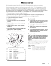
See the separate component instruction manuals for individual component maintenance procedures.
Access to some system components requires that you remove the shields. The following steps are for shield
removal. Shield replacement is the reverse of these steps, so make sure you take notes on the proper hose
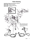
connections. Depending on your system, see the Parts Drawings on pages 11 and 13 for number call-outs.
You cannot remove the front shield assembly while the pump and shields are mounted on the stand; thus, before
you can remove the front shield assembly (1) or the back shield (25), you must do the following steps:
1. Disconnect the gun air hose from the gun air regulator.
2. Disconnect the gun fluid hose from the fluid pressure regulator nipple (28) or surge tank nipple (40).
3. Remove the screws (32), nuts (23), and washer (22) from the mounting bracket (45).
4. Lift the entire system from the stand (41)
Front Shield Assembly (1)
1. Disconnect the pump air hose from the pump air
regulator.
2. Loosen, but do not remove, the two front pump
foot screws (24).
3. Loosen, but do not remove, the two top shield
screws (32).
4. If your system has a fluid pressure regulator (40),
make sure the T–handle is horizontal.
5. Pull the front shield assembly free of the system.
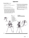
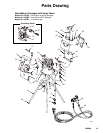
Fig. 2
8263A
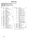
Ref.
No. Part No. Description Qty.
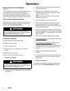
1a 192995 SHIELD, front 1
1b 111804 REGULATOR, air
See instruction manual 308167
2
1c 160430 GAUGE, pressure 2
1d 114362 VALVE, ball 1
1e 159840 ADAPTER 2
1f 188077 NIPPLE 1
1g 114369 FITTING, tube 1
1h 114370 FITTING, tube 1
Front Shield Assembly Orderable Parts
1a
1b
1c
1d
1e1f
1g
1h
pump air
regulator
gun air
regulator
Back Shield (25)
1. Disconnect the hose (18) that runs from the fluid
pressure regulator (40) or surge tank (30) to the
fitting on the pump outlet pipe tee (5).
2. Loosen, but do not remove, the two top shield
screws (32).
3. Loosen, but do not remove, the two back pump
foot screws (24).
4. Pull the back shield free of the system. The fluid
pressure regulator (40) or surge tank (30) stays
mounted to the back shield.
Gauge Lense Covers
Clear, stick-on/peel-off lense covers are available for
the gauges. These covers protect the gauge lenses
from spray. When they get too dirty to read the
gauges, they can be peeled off, discarded, and
replaced.
NOTE: Several of these lense covers can be stacked
on the lense, and the gauge will still be clearly legible.
Then, as each lense cover gets dirty, only that one
layer will need to be peeled off.
Order as follows:
240441 for 2.5-inch gauges; package of 25
sheets, 12 lense covers to a sheet
240442 for 2-inch gauges; package of 25
sheets, 12 lense covers to a sheet