


Installation
309295L 11
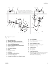
Connect the Fluid Line
1. Before connecting the fluid line (N), blow it out with
air and flush it with solvent. Use solvent which is
compatible with the fluid to be sprayed.
2. Install a fluid regulator (M) on the fluid line to control
fluid pressure to the gun.
3. Install a drain valve (U) near the pump outlet.
4. Connect the fluid line to the 1/4 npsm gun fluid inlet
(W).
5. Before running any paint through the spray gun,
flush it out with a compatible solvent.
Filter the Fluid
Install a fluid filter (K) at the pump outlet to remove parti-
cles and sediment which could clog the spray tip.
The gun includes an inline fluid filter (1) for additional fil-
tration.
Select a Spray Tip
The fluid output and pattern width depend on the size of
the spray tip, the fluid viscosity, and the fluid pressure.
Use the Spray Tip Selection Chart, page 46, as a
guide for selecting the appropriate spray tip for your
application.
Refer to the gun operation manual to install the spray tip.
WARNING
Skin Injection Hazard
The fluid drain valve (U) is required in your
system to assist in relieving fluid pressure in
the displacement pump, hose and gun. Trig-
gering the gun to relieve pressure may not
be sufficient. Install a drain valve close to the pump's
fluid outlet. The drain valve reduces the risk of seri-
ous injury, including fluid injection and splashing in
the eyes or on the skin.
WARNING
Skin Injection Hazard
To reduce the risk of a fluid injection injury,
always follow the Pressure Relief Proce-
dure, page 24, before removing or installing
the spray tip, air cap, or tip guard.