


Repair
24 311001G
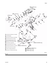
Reassembly
1. Install the tube gasket (22*) in the gun. Handtighten
the fluid tube connector (C) into the gun’s fluid inlet.
Handtighten the air inlet fitting (17) and screw (20).
Torque the fluid tube connector to 150-160 in-lb
(17-18 N•m). Torque the air inlet fitting to 175-185
in-lb (20-21 N•m). Torque the fluid tube bracket
screw to 50-60 in-lb (6-7 N•m). See F
IG. 44.
2. Install the inline fluid filter (12) into the base of the
fluid tube. Screw the fluid inlet fitting (18) into the
base of the tube. Torque to 175-185 in-lb (20-21
N•m). See F
IG. 44.
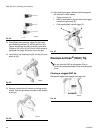
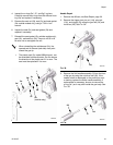
3. Place the new u-cup (7*) on the seal installation tool
(28*), with the u-cup lips facing the tool as shown in
F
IG. 42. Push the u-cup into the back of the gun until
you feel a definite snap.
4. Lubricate the front end of the air valve assembly
(8*). Gently slide the air valve assembly into the
back of the gun, passing through the u-cup (7*), as
far as it will go. Be careful not to damage the u-cup.
See F
IG. 44.
5. Slide the seat (10) onto the shaft (9). Be sure that
the tapered end of the seat is toward the thicker end
of the shaft. Carefully insert the shaft (9) and seat
(10) in the air valve (8*).
6. Install the two springs (15 and 19). Screw the spring
cap (11) into the back of the gun body. Torque to
175-185 in-lb (20-21 N•m).
7. Lightly lubricate the needle assembly o-rings and
shaft where the packing slides. Be sure that the
o-ring (2a*) is in place in the gun body (1).
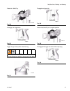
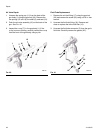
8. Insert the fluid needle assembly (2) into the front of
the gun. Use the nut driver (29) to screw the fluid
needle assembly into the gun body (1) and torque to
50-60 in-lb (6-7 N•m). See F
IG. 43.
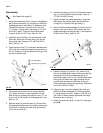
9. Install the trigger (3), pivot pin (13), and nut (14).
Use low strength thread locker and be sure that the
brass piece of the fluid needle assembly (2) is
behind the trigger. See F
IG. 44. Lubricate both sides
of the pivot pin where the trigger contacts the pin
and lubricate the boss on both sides of the gun
where the trigger contacts the gun body. Torque the
nut to 20-30 in-lb (2-3 N•m).
10. Trigger the gun to pull the needle back while you
screw the diffuser assembly (5) into the gun body
(1) using the gun tool (30). Torque to 155-165 in-lb
(18-19 N•m). When properly tightened, the flange
will bottom out on the gun.
11. Attach the retaining ring (6), air cap (21), and spray
tip (33)✖.
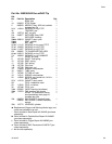
• See Repair Kits, page 20.
F
IG. 42
TI6578A
7*
28*
Lubricate lightly.
Lips face out of gun body.
3
8
3
8
FIG. 43
TI6575A
2†
29
1
2a*