


Setup
8 311001G
Setup
Flush Before Using Equipment
1. The equipment was tested with lightweight oil, which
is left in the fluid passages to protect parts. To avoid
contaminating your fluid with oil, flush the equipment
with a compatible solvent before using the equip-
ment. See Flushing and Cleaning, page 14.
2. Relieve the pressure. See Pressure Relief Proce-
dure, page 10.
Select a Spray Tip and Air Cap
The fluid flow and pattern width depend on the size of
the spray tip, the fluid viscosity, and the fluid pressure.
See Spray Tip Selection Chart, page 30. Contact your
Graco distributor for assistance in selecting an appropri-
ate spray tip for your application.
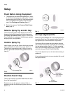
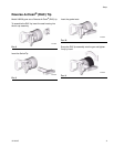
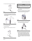
Install a Spray Tip
Install a spray tip in the gun. Ensure that the tip locating
tab is positioned in the slot of the air cap. See F
IG. 5.
Tighten the air cap retaining ring (6) firmly by hand to
ensure a good seal between the tip gasket and the dif-
fuser (5).
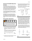
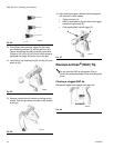
Position the Air Cap
The air cap and spray tip position determines the direc-
tion of the spray pattern.
Rotate the air cap (the spray tip rotates with it) as
needed to achieve the desired spray pattern direction.
See F
IG. 6.
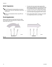
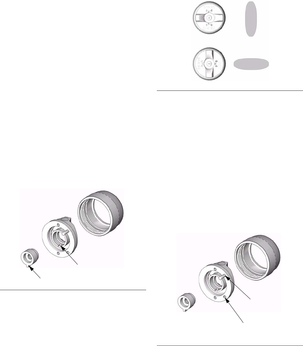
Air Cap Alignment Pin
Model G15 guns (288844) use an air cap alignment pin
to position the air cap. The standard location of the air
cap alignment pin is the horizontal air cap position.
If you would like to change the spray pattern direction,
use a needle nose pliers to unscrew the pin and relocate
it to the desired position. See F
IG. 7. When relocating
the pin use low-strength thread locker. Torque to 1.5-2.5
in-lb (0.2-0.3 N•m). DO NOT OVERTIGHTEN.
The air cap alignment pin can be removed according to
preference.
Air cap alignment pins do not come standard with model
G40 guns (249242).
F
IG. 5
TI6847A
Tip Locating Tab
Slot
F
IG. 6
F
IG. 7
TI6558A
TI6847A
Horizontal
Air Cap Position
(standard)
Vertical
Air Cap Position