-12-
G0458 18" Open End Belt/Drum Sander
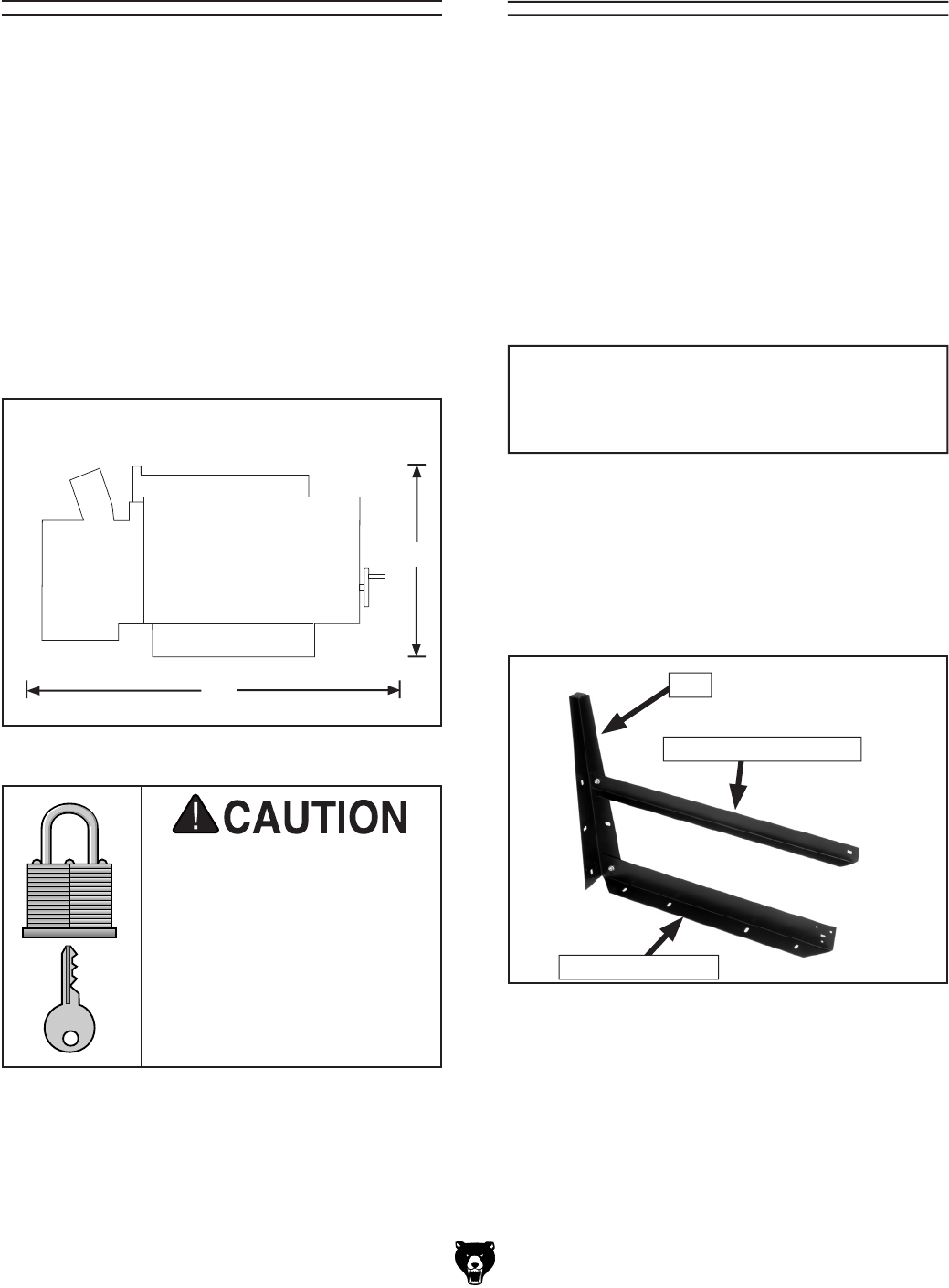
Figure 3. Model G0458 Working clearances.
Floor Load
The weight and footprint size for your machine is
located in the machine data sheet.
Some residen-
tial floors may require additional reinforcement to
support the machine, workpieces, and operator.
Working Clearances
Consider existing and anticipated needs, size of
material to be processed through each machine,
and space for auxiliary stands, work tables or
other machinery when establishing a location for
your new machine. See Figure
3 for the minimum
working clearances.
Unsupervised children and
visitors inside your shop
could cause serious per
-
sonal injury to themselves.
Lock all entrances to the
shop when you are away and
DO NOT allow unsupervised
children or visitors in your
shop at any time!
Site Considerations
Figure 4. Top and bottom long brackets secured
to a stand leg.
Components and Hardware Needed: Qty
Carriage Bolts M8-1.25 x 15 .............................16
Serrated Flange Nuts 12mm ............................16
Top Short Brackets .............................................
2
Bottom Short Brackets .......................................
2
Stand Legs .........................................................
4
Top Long Brackets ..............................................
2
Bottom Long Brackets ........................................
2
We recommend assembling the stand upside
down. To make it easier, have an assistant hold
the pieces while you assemble the stand.
Stand
Top long bracket
Bottom Long Bracket
Leg
To assemble the stand:
1. Mount a top and bottom long bracket to a
stand leg and loosely secure with two M8-
1.25 x 15 carriage bolts and serrated flange
nuts as shown in Figure
4.
35"
24"
NOTICE
Do not final tighten stand bolts until the
stand components have been assembled.


