


G0474/G0475 Sandblasters
-9-
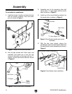
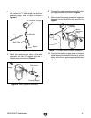
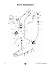
Figure 5. Gauge/air supply control installation.
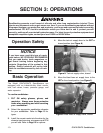
Figure 6.
Water separator assembly.
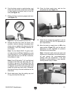
Figure 7. Air supply control system installation.
6. Attach to the manifold one of the remaining
ball valves and
3
⁄8" hose nipple, the red hose,
pressure gau
ge, and the pipe as shown in
Figure 5.
8. Connect the water separator assembly to the
air supply Manifold as shown in Figure 7.
9. Now connect the gauge and water separator
assembly to the top of the tank as shown in
Figure 7.
7. Install the remaining ball valve to the water
separator with two
3
⁄8" nipples, and the
3
⁄8"
female nipple as shown in Figure 6.
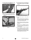
10. Connect the tank air supply hose to the sand
outlet elbow at the bottom of the tank, and the
other end to the air pressure gauge ball valve
nipple.
Air Pressure Gauge
Pipe
Manifold
Ball Valve
Nipple
Nipple
Ball Valve
Nipple
Female Nipple
Air Supply
Manifold
Water
Separator
Assy.
Tank